<
Click here for a stereo electronic volume control
using a single 6HS8 sharp cutoff tube.
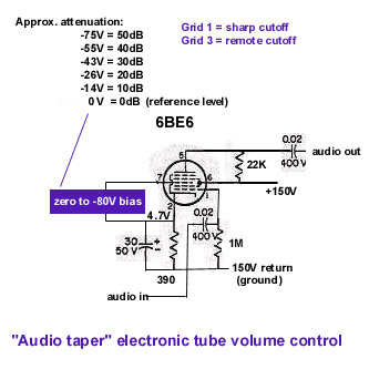 This uses a common 6BE6 or 12BE6 pentagrid tube usually found in radios.
The input audio is fed to grid 1 (which has a sharp cutoff curve, see below). A
control
voltage is applied to grid 3 (which has a remote cutoff curve, also see below). Zero
volts
measured from the cathode gives us our reference level of 0dB. -14V
gets us about 10dB attenuation. Double that voltage and that gets us
about 20dB. Triple gets us about 30dB. Quadruple gets us about 40dB,
and max attenuation of 50db happens around 75V and beyond. This
would be a kind of audio taper attenuation on linear increase of
negative
voltage. You'll have to hand select a pair of tubes that track
each other reasonably close for a stereo system.
This uses a common 6BE6 or 12BE6 pentagrid tube usually found in radios.
The input audio is fed to grid 1 (which has a sharp cutoff curve, see below). A
control
voltage is applied to grid 3 (which has a remote cutoff curve, also see below). Zero
volts
measured from the cathode gives us our reference level of 0dB. -14V
gets us about 10dB attenuation. Double that voltage and that gets us
about 20dB. Triple gets us about 30dB. Quadruple gets us about 40dB,
and max attenuation of 50db happens around 75V and beyond. This
would be a kind of audio taper attenuation on linear increase of
negative
voltage. You'll have to hand select a pair of tubes that track
each other reasonably close for a stereo system.
Or you could have a trimpot for each "attenuation grid" (G3's)
where the one end of the trimpot is tied to the respective cathode and the wiper goes to the grid.
All the tops of the trimpots would be connected together and go to your
volume control pot. That way you can adjust the grid voltage of each
from the volume pot voltage to zero volts with respect to the cathode.
You'd adjust your trim
pots to equalize all the attenuations. Granted, it would only be able to
match at one point, but I'd bet it would be close. (Sheldon D. Stokes) Be sure
to make the trimpot high resistance so one won't draw significant current from
the cathode circuit, and bypass the G3's to avoid noise pickup. Or use fixed
bias of -4.7V on the G1's and ground the cathodes.
Applications: Vary the volume from a remote location without having to
pipe the audio to the remote location and back again. You could use
an infrared remote (like a TV remote) and not have to pass the audio
thru
the solid state attenuator that the remote receiver
circuitry controls. Rather than that
use that solid state attenuator and a buffer circuit to create the zero
to -75V
needed by the 6BE6 circuit above. Thus the audio sees only vacuum
tubes.
The 6BE6 plate circuit could also act as an output tube driver.
 G1 to plate if "volume control" set to -6V.
 G1 to plate if "volume control" set to -3V.
 How G3 varies plate current.
 G3 diverts plate current to the screens.
Full data
sheet on the 6BE6.
Another tube you can use as an electronic volume control: 6HS8
 To avoid the problems of a pair of 6BE6's not tracking each
other in a stereo system, you could use a tube with a single
grid 1 and a pair of grid 3's and a pair of plates. Like the
6HS8. This is an otherwise worthless TV tube.
Grid 1 sets the variable gain of the whole tube (to keep the
dissipation of the screen within spec, the range stops at 0.6V), and
say the left channel feeds G3a and left channel out taken off
of P3a. Likewise for the right channel. Thus both channels will
track each other exactly. With the cathode
held steady, there is virtually no crosstalk, about -55dB. I used some 1N4148
diodes to provide a fixed bias to the cathode. The 47K resistor
from the cathode to B+ keeps a quiescent current thru the diodes
to maintain the voltage drop if the tube is forced into zero
gain and thus cutoff. Like the other circuit, this one
could also be used to drive single ended output tubes. The
6HS8 would look like a pair of triodes at lower plate currents to the audio signal.
At higher plate currents grid 1 starts to limit things, as you can see
in the diagram "Average Plate Characteristics" below.
As such, one can determine rough figures for µ for a G3 to its corresponding plate.
µ is the ratio of the change of
plate voltage to a change in the control grid in the opposite
direction, under the condition that the plate current remains
unchanged and other electrodes have unchanged voltage. I get a rough
value of µ = 55 for what the audio signals see. That is, from
a G3 to its corresponding plate. The µ doesn't change much
with different settings of G1 bias. What variation I got (µ = 48 to 64 for
G1 = -1.2V to -4.4V respectively)
was probably due to the curves seen in the diagram "Average Plate Characteristics" below.
What does change a lot is
plate resistance. At G1 = -3V the Rp = 960K. At G1 = -1.3V,
the Rp = 214K. And thus the transconductance (gm) changes.
gm is µ/Rp. So for G1 at -3V, gm = 55/960K = 57 µmhos. At
G1 = -1.3V, gm = 55/214K = 257 µmhos. As the gain of the
circuit = (µ*Rload)/(Rload+Rp) or (gm*Rp*Rload)/(1000000*(Rp+Rload)).
We have seen that Rp changes drastically by G1 bias changes,
and thus the gain changes because of G1 bias changes.
To avoid the problems of a pair of 6BE6's not tracking each
other in a stereo system, you could use a tube with a single
grid 1 and a pair of grid 3's and a pair of plates. Like the
6HS8. This is an otherwise worthless TV tube.
Grid 1 sets the variable gain of the whole tube (to keep the
dissipation of the screen within spec, the range stops at 0.6V), and
say the left channel feeds G3a and left channel out taken off
of P3a. Likewise for the right channel. Thus both channels will
track each other exactly. With the cathode
held steady, there is virtually no crosstalk, about -55dB. I used some 1N4148
diodes to provide a fixed bias to the cathode. The 47K resistor
from the cathode to B+ keeps a quiescent current thru the diodes
to maintain the voltage drop if the tube is forced into zero
gain and thus cutoff. Like the other circuit, this one
could also be used to drive single ended output tubes. The
6HS8 would look like a pair of triodes at lower plate currents to the audio signal.
At higher plate currents grid 1 starts to limit things, as you can see
in the diagram "Average Plate Characteristics" below.
As such, one can determine rough figures for µ for a G3 to its corresponding plate.
µ is the ratio of the change of
plate voltage to a change in the control grid in the opposite
direction, under the condition that the plate current remains
unchanged and other electrodes have unchanged voltage. I get a rough
value of µ = 55 for what the audio signals see. That is, from
a G3 to its corresponding plate. The µ doesn't change much
with different settings of G1 bias. What variation I got (µ = 48 to 64 for
G1 = -1.2V to -4.4V respectively)
was probably due to the curves seen in the diagram "Average Plate Characteristics" below.
What does change a lot is
plate resistance. At G1 = -3V the Rp = 960K. At G1 = -1.3V,
the Rp = 214K. And thus the transconductance (gm) changes.
gm is µ/Rp. So for G1 at -3V, gm = 55/960K = 57 µmhos. At
G1 = -1.3V, gm = 55/214K = 257 µmhos. As the gain of the
circuit = (µ*Rload)/(Rload+Rp) or (gm*Rp*Rload)/(1000000*(Rp+Rload)).
We have seen that Rp changes drastically by G1 bias changes,
and thus the gain changes because of G1 bias changes.


Full
data on the 6HS8.