
 What you don't
want to hear is the 3rd harmonic, which sounds "harsh" and is not at all "musical".
What you don't
want to hear is the 3rd harmonic, which sounds "harsh" and is not at all "musical".  You want that down at least 60dB.
This might be understood if you look at the frequencies of piano keys.
The A2 key makes a tone at 110Hz, and the
2nd harmonic of that puts you exactly atop the A3 key, at 220Hz. Now
the 3rd harmonic of the A2 key would be 330Hz, but that
doesn't come out atop any other piano key. It's between keys E4 and F4,
closer to E4, which is 329.628Hz.
But that's enough off to make it sound bad. Or maybe no musician would
want to play A2 and E4 together "You hit the wrong note, Billygoat!".
I'm not a musician, so YMMV.
Anyway it still sounds bad.
Push-Pull amps tend to cancel the 2nd H
but sum the 3rd H, which may explain the popularity of "single ended tube" (SET)
amps. In any event one has to avoid getting too much
(above around 60dB)
intermod distortion, which also sounds bad. But a small amount of 2nd H can sound nice.
Tubes handle excess peak signals better than solid state, but excess peaks can't happen
inside a CD player. As the CD medium itself has a hard and fast peak signal
capability limit. Not like say a microphone amp in a recording studio. But
tubes in a CD player are still worthwhile.
You want that down at least 60dB.
This might be understood if you look at the frequencies of piano keys.
The A2 key makes a tone at 110Hz, and the
2nd harmonic of that puts you exactly atop the A3 key, at 220Hz. Now
the 3rd harmonic of the A2 key would be 330Hz, but that
doesn't come out atop any other piano key. It's between keys E4 and F4,
closer to E4, which is 329.628Hz.
But that's enough off to make it sound bad. Or maybe no musician would
want to play A2 and E4 together "You hit the wrong note, Billygoat!".
I'm not a musician, so YMMV.
Anyway it still sounds bad.
Push-Pull amps tend to cancel the 2nd H
but sum the 3rd H, which may explain the popularity of "single ended tube" (SET)
amps. In any event one has to avoid getting too much
(above around 60dB)
intermod distortion, which also sounds bad. But a small amount of 2nd H can sound nice.
Tubes handle excess peak signals better than solid state, but excess peaks can't happen
inside a CD player. As the CD medium itself has a hard and fast peak signal
capability limit. Not like say a microphone amp in a recording studio. But
tubes in a CD player are still worthwhile.

As for op-amps, some can sound bad even though they spec great. The specs are
in relation to peak signal amplitudes, but music has low level intervals. Things
like crossover distortion can crop up badly at those points of time. The usual
op-amp output stage consists of a complementary or quasi complementary pair of
transistors in class B. The heavy amount of feedback tries hard but can't get rid of
all the crossover distortion. Especially if the op-amp has significant open loop phase
shift at audio frequencies from input to its output. Some have 90 degrees of open loop phase
shift at audio frequencies. Many have uneven phase shifts in the audio frequency range,
which can muddy transient response when amplifying music signals.
Phase shifts can move parts of the waveform around in terms of time
and that can make the characteristics of the feedback loop become rather
"interesting".
The feedback signal can arrive at the wrong times to correct the errors
completely.
Crossover distortion problems tend to be very true of any op-amp that is
designed to consume a minimum of power. Op-amps designed to do class AB
should have
less of this problem. Some op-amps benefit when forced into "single
ended" class A
mode. Drawing or sinking a more or less constant current from
or to the op-amp's output will do that. That would get rid of the
crossover
distortion issue. Just be sure the op-amp doesn't run out of
current ability. The tube circuits in this web page don't use any
feedback other than that
small amount you get internally in triodes. No "fun" feedback loops.
Another issue with op-amps used as IV converters is that of slew rate
(as pointed out by Lynn Olson).
Or lack of enough thereof. Current output DACs produce spectral energy
upwards to around 30MHz or
even higher, depending how you measure it. Most op-amps you find in CD
players have a slew rate of around 10V/usec, but the DAC here would need
an op-amp that could do 1000V/uSec. The op-amp inside the PCM61 DAC
chip has a slew rate of only 12V/uSec.
With the slow slew rate op-amp the virtual ground the DAC is feeding
stops being at ground until the op-amp slews its output voltage to draw
the current thru the feedback resistor to get the virtual ground back to
zero volts. You'd see triangular voltage spikes of a few volts during
the time the op-amp is slewing. And the slope is pretty constant, so the
area of the trangle would vary non-linearly against differences of the
size of the signal step out of the DAC. This trangular region you see on
the virtual ground is essentially that you find missing from the
op-amp's voltage output.
A possible solution to this would be to use a high speed op-amp in place
of the original op-amp. The 10V/usec slew rate would be more than
enough for
use in purely analog audio work, but DAC chip outputs have the above
mentioned unfiltered supersonic content you need to contend with.
Look for a high "unity gain bandwidth" or "Unity gain crossover
frequency" open loop spec, something above 50MHz would be good.
Op-amps designed for video work would be good for this. But use RF
grounding techniques, like ground planes and
close bypassing to keep things stable.
Your first desire is an op-amp with a very high slew rate
specification. But what fun is that if you don't use vacuum tubes....
And a CD player with direct heat filament tubes
An advantage of modifying a CD player vs. building a separate "DAC" box is that there would not be any jitter noise issues due to the PLL the separate box would require. The CD player has a master crystal oscillator that the internal DACs are clocked off of. Crystal oscillators that are free running are quite jitter free. The transport (here I am talking about the mechanical device that holds and spins the CD, and has the laser and the digital signal demodulators) is driven by servo loops that maintain a reasonably constant stream of digitized audio off the CD itself. Any timing variations are removed by a FIFO stage between the transport and the DACs. You could tap this master clock oscillator and use it instead of the PLL in your separate "DAC" box to avoid jitter, if you decide to go that way.
A lot of DACs expect to send current into a virtual ground. Which is provided by an op amp. The reason for the virtual ground is that many DACs make an analog current that must be pumped into a virtual ground. Most DACs use an R-2R ladder of resistors and switches. Depending on which way these resistors and switches are hooked up, the DAC may or may not like running into a load resistor used as a current to voltage converter.
There are two ways of doing an R-2R ladder DAC. One way
is the configuration of the type in Fig 1.
The I out pin in this case has a constant impedance of R
for all possible data words. It looks like a variable
voltage source with a Thevenin equivalent resistance of R.
The data sheet of the Burr Brown PCM61 (the DAC in the CD player
I was hacking, it's obsolete but TI makes similar ones, such as the
PCM56P)
specifies R as having an impedance of 1.2K ń 30%.
The PCM61 chip appears to use this configuration. I found
that a 1K resistor to ground yields a linear signal of
1V peak to peak. The data sheet mentions a glitch spec
of 360ns when using a 1K resistor on the I out pin.
So this would appear to be a valid design. Adding a small cap of 4700pF to ground
to filter clock noise (the CD player uses 4X oversampling)
and another cap to the output terminals works fine. You could
instead use a T network of a pair of 1mH coils and a 3300pF cap between the
DAC current output pin and the 1K load resistor (values not critical)
per channel for better filtering (about 12 to 15dB down at 176KHz than without).
You want to avoid this supersonic
clock noise from intermodulating in your amp. So I
don't need tubes or solid state for the analog audio! The impedance
thus will be 545 ohms, which should be plenty low enough
to drive the audio signal thru any interconnects you use.
The audio would feed directly from the output RCA jacks
to your favorite tube amplifier line inputs. Can't do better than
that! (I assume that 1V p-p audio isn't too low for the amp.
If it is, you could build your favorite tube voltage amplifier stage to
bring it up.)
Other DACs of this type might have ESD diodes that might
clip the voltage swing to a lower value.
Data sheets don't usually mention what style of R-2R ladder is
used, but if there is a spec for impedance for I out, it's a
good bet it's this configuration.


The other configuration of R-2R ladder DAC (Fig 2) does not have a constant
output impedance.
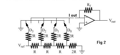
It can only work correctly if it feeds
into a virtual ground. The reason for this configuration is that
it places a constant load on its voltage reference. See Fig 21 and 22
for an example of the errors of this kind of DAC when you try to use it with a
load resistor.
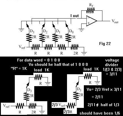
Here's a simulation of this sort of DAC, but with just 4 bits. You can see
uneven steps in what should be a sawtooth wave in the first plot below.
Here the DAC was feeding into a 1K ohm I to V resistor (a bit big, but
done for clarity; even a realistic 100 ohms would have audible distortion).
Note that the distortion isn't a smooth curve; some steps have bigger
changes than others. Some are backwards! This creates a rather hashy sound.
What is doing this is the fact that the R2R voltage divider's
various tap voltages are no longer constant, as the loading on
them are now varying. Here 8 is digital word 1000, and 4 digital word
0100.

The next plot shows the same DAC feeding into a virtual ground of
an op amp. Here it looks linear and not distorted.
Now if your player uses this sort of DAC, then you need the virtual ground. Or change the DAC, but that is beyond the scope of this page. If you do decide to go that way, you'll have to find DACs that can accept the particular format of digital signals (one of various flavors of parallel or serial data streams) the old DAC used. Depends on what the other digital chips on the board did with the signals after they got them off the disc, where the CD audio format standard resides.
Delta sigma DAC's (sometimes called "1 bit DACs") should easily interface with tubes, as long as there is no analog buffer/filter op amp in the audio path inside the chip. These have either a voltage or current switch "high or low" that is switched at a very high rate. Some even specify a current to voltage resistor on the output (which works out great for us). And it is expected that there be a low pass filter to average these out to get the analog signal output. An RC network should be enough to do that. Some DACs use a combination of resistor ladders and delta sigma circuits. These would have the same issues as the regular resistor ladder DACs above.
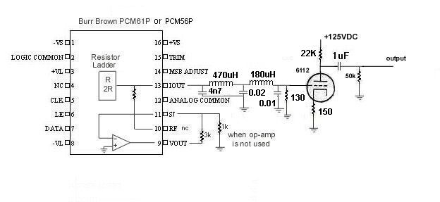

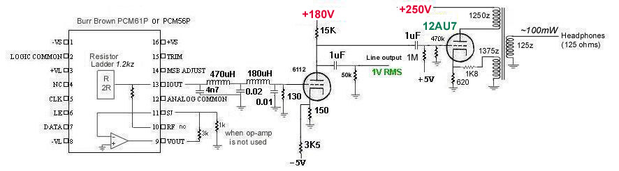
I decided that I wanted more line drive, so I used a 6112
twin triode subminiature tube. The DACs outputs are filtered
to remove clock noise, and then directly feeds the grids.
I added another pair of 150 resistors at the grids to ground,
as the original DAC voltage swing was a bit too big for
the triodes to handle linearly. This makes for loads of
130 ohms. The filter component values changed from the above.
Yes, those are TV peaking coils I used.
(Be mindful of ESD getting into the DACs, I blew one up
that way (DUH!). I found that the PCM56P (still in
production but only 16 bits) also works well here. I
used them until some replacement PCM61P's come in. Had to
use a 74S374 configured as a pair of digital delay lines
to get the top 16 bits of the 18 bits in the '56's
correctly. See timing diagram down below.
That's that kludge of sockets and wires
under the tube in the picture below.) The '61's just
arrived and I took the kludge out.
150 resistors unbypassed in the cathodes are used for
cathode feedback. 22K plate resistors then feed into 1uF
poly caps. You can see where we are operating on the
6112 tube curves below. And there are resistors from the output jacks
to ground, mainly to charge or discharge the coupling caps.
This is to protect the inputs of a stereo amp from seeing
transient bursts of B+ thru the caps upon power up or
power down.
6112 data sheet
PDF


Thus it should be perfectly valid to be able to use a hundred ohm resistor to ground for the I/V
conversion, and then feed the resulting voltage into your
favorite pre-amp circuit, be it transistor, op-amp, or tube
to get it up to line level to feed to your audio amp.


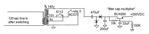
I also redid the power supply. A power transformer from my
old "ugly 6KY8 amp" is mounted on the back and supplies 140VAC to
feed a voltage doubler. Also 6V for the 6112 and 12V thru a resistor
for the 8CG7/8FQ7. The pass transistor is one meant for
horizontal output service in TVs and monitors, and can take
high voltage. This transistor isn't really a regulator, it's
more of a filter cap multiplier.

And some test results:
The DAC's output, 6112 grid:
These are the line output (6112 plate) (I need better power supply filtering here, lots of 120Hz harmonics):
These are the headphone amp output at the headphone jack:
 About 0. 32% 2nd harmonic into the headphones.
And an IMD test (1KHz and 1.1KHz tones) full amplitude (DAC output, line output and
headphone jack):


Looks to be about the same THD distortion as above...
Here I changed the 8FQ7 to a 12AU7.
The 12AU7 is quite similar except for lower plate dissipation.
Here I redid the DAC tube preamp into a "SRPP" circuit. Uses a
pair of 6111 submini tubes. These tube shave a mu of 20, gm of 5000
and plate resistance of 4K. This circuit offers lower output impedance
and lower distortion. Measurements show the 2nd harmonic
around 58 dB down and nothing else above a lower noise floor than those above. Output
level is lower than with the 6112, but is cleaner. If you need to,
use a lower noise from the heater tube for the bottom tube. As these
are twin triodes, one tube is used for the bottom left and right
channels, and the other twin triode used for top left and right channels. Using
sockets like I did here allows tube rolling. A noisier tube can be
used for the top tube.

Here I added a driver stage betwen the SRPP and the headphone
output stage, with a different transformer, 10K to 8 ohm.
6111 datasheet PDF


I modified an old CD player by installing a filament tube to take the
DAC's output and amplify it to line level. The machine I modified was
a "Fisher" AD834. Nearly the same internals as the Yahama machine that was
my first CD player I bought in 1984. It uses a single DAC chip, a Burr Brown PCM53V for
both channels. 2X oversampling. Subsequent circuitry separates the left and right
channels. Not a great test bed, but I figured I'd make it a mono CD
player. Looking at the DAC chip's output, you'd see alternating left
channel and right channel audio levels at 176.4KHz rate (twice the 2X CD
sampling rate of 88.2KHz). This would look somewhat similar to the
waveform seen at the FM detector of an FM stereo receiver as it
feeds the multiplex decoder. Differing frequencies though
(88.2Khz instead of 38KHz). So if
I low pass filter the DAC chip's output, I'd get L+R aka mono. This
low pass filter then feeds the tube's grid 1. Ideally I'd use the current output
version of this DAC, but as I can't find any I just used a resistor voltage
divider to reduce the audio signal voltage feeding the grid to 200mV p-p.
The tube, a submini
directly heated pentode 5678 is connected as a triode. The audio
output is taken off the plate and G2 circuit thru a coupling cap.
B+ is around 110V. This tube is designed to expect DC on the filament
applied in a specified polarity. The G1 grid is designed to expect
some portions
of the filament to be more positive than others, but to draw
equal amounts of current throughout the length of the filament.
Thus the polarity spec that pin 3 is the negative filament supply,
and pin 5 the positive. I used a 5V regulator chip to provide
filament current but thru a pair of resistors in series with the
filament in the middle. This provides bias for the tube of 1V,
to produce plate current of around 1.8ma.
Using a custom burned test CD I tested this circuit with full
amplitude sine waves to see how much distortion. I see about
-54dB of 2nd harmonic, and no 3rd harmonic. Though there is a
little 4th harmonic. But it sounds good.
Only thing is that these small filament tubes don't glow...
Use a pair of these circuits for stereo, and current to voltage
converter resistors with current mode DAC chips for real work.
Data for the 5678 tube can be downloaded from:
Frank's page and
also at Frank's

 The SMD's are the added 10K resistor and 22uF cap next to the DAC chip. I wanted to minimize the
amount of stray capacitance hanging on the summing junction.
The SMD's are the added 10K resistor and 22uF cap next to the DAC chip. I wanted to minimize the
amount of stray capacitance hanging on the summing junction.
A thought comes to mind: In players with a pair of DAC chips like this PCM53-V, one may be able to minimize the
op-amp's existance by connecting a 100 ohm resistor from ground to pin
21, the summing junction. Disconnect pin 17, as the signal here will be very low and not usable anymore, if it ever was...
And feed this summing junction pin to a gain stage
like one of the other CD player mods
above, like the SRPP or the triode voltage amp. But in this Fisher CD player, they have only one DAC
chip for both channels, and they used sample and hold circuits to
separate the left and right channels. So this idea wouldn't make sense here.
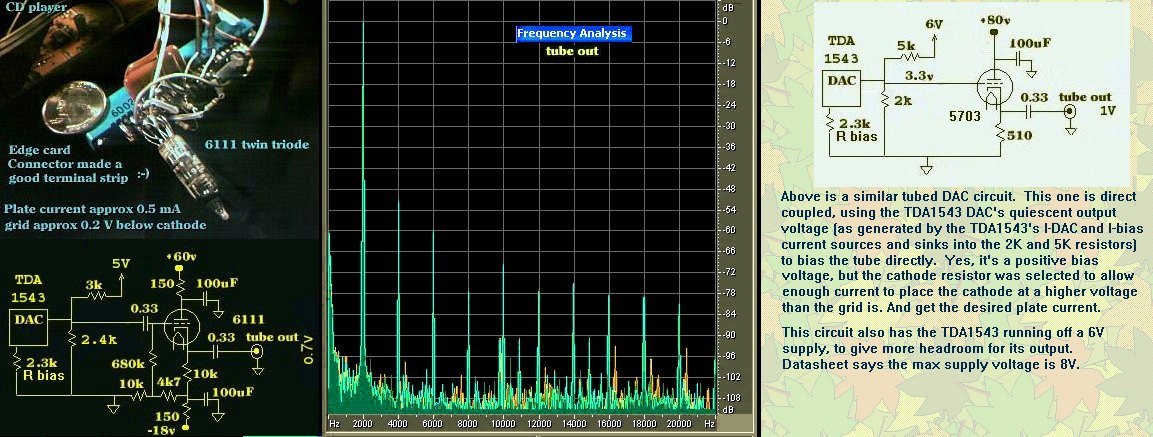
I modified my old Magnavox CDB600 (really a Philips machine) CD player.
It uses a TDA1543 "twin DAC" DAC
chip, and it used to feed op-amp I/V converter circuits. But I found
that this DAC
chip seems quite happy to feed a resistive load for the I/V circuit.
This DAC chip
has, for each channel, a constant source current generator "Ibias"
(connected to Vcc 5V), and a
varying (to the music)
sink current generator "Idac" (connected to ground). The other ends of
these current sources
join together to create the left or right outputs.
The difference current between these two goes into/from the
resistor load. It wants a bias of about 2.2V for this resistor load.
This 2.2V
bias needs to source or sink current. A conventional voltage regulator
chip would only
source current but not sink current, so that won't work. But an easy way
to create this
is to use a voltage divider network, 3k resistor from +5V, 2.4K to
ground, to create a
thevanin equivalent of a 1.3k resistor going to 2.2V. The DAC develops
something like
1Vp-p of audio, which feeds a cathode follower triode grid. I used
existing power supply
voltages inside this machine, combined with a voltage doubler circuit,
to get about 80V for this tube circuit (not a lot, but it seems happy).
The power supply had plus
and minus 20V from a centertapped power transformer secondary feeding a
bridge
rectifier. Another bridge rectifier with its negative output tied to the
+20V
line, and one "AC" input thru a 100uF cap connected to one side of the
power
transformer secondary, and another such cap connected to the other side
of the
transformer secondary to the other "AC" input to the bridge forms the
doubler to
get +40VDC (measured from the "+" terminal to the "-" terminal) more out
of
the "+" terminal of the bridge, with a filter cap from that "+" terminal
to
the "-" terminal of that bridge. That gives us about 60V to ground.
The tube circuit uses the -20V line as its "ground" so it sees about 80V
from the -20V line to the +60V line.


The TDA1543 power supply I kept at 5V.
You could just use a resistor to ground if you set Ibias to a value higher than Idac
peaks at. I wanted to maintain the average voltage bias the TDA1543 saw with the op-amp circuit,
so operating it into a resistor equivalent into a voltage similar to Vref seemed a
sensible thing to do. Looked at a
resistor going only to ground. But you must set your Ibias to be larger than the max
the Idac ever sinks. And the current Ibias - Idac goes into your resistor. As long
as Ibias is high enough to keep Idac operating correctly (voltage higher than something
like 0.6V?) that should work. A concern I had was that the Idac circuit might not
work quite right if the output voltage got too close to ground. The clipping I
experienced before I did my above circuit must have been do to insufficient Ibias
on Idac peaks. My use of the 2.2V equivalent source avoids that. It allows Idac to
exceed Ibias. Note that I showed only one of the two analog audio channels in the TDA1543 DAC diagrams.

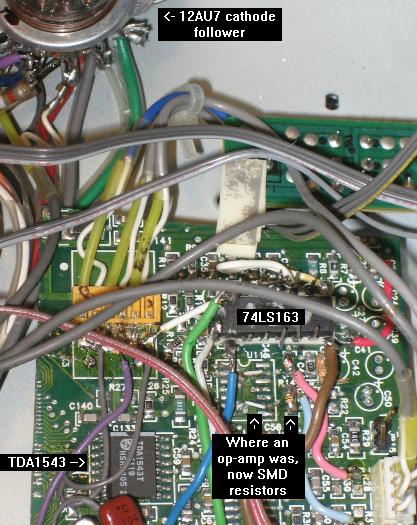
I inserted an extra DAC chip in a Sony CDP397. Inside is mostly empty space. It uses a CXD2500, which
produces a set of signals similar but not exactly I2S, which is what the TDA1543 (the new DAC chip)
expects. The main issue is that the LRCK signal changes state too early, by 8 sample bit
clocks. The TDA1543 grabs the first 16 bits it sees when this LRCK changes state,
and ignores any more bits that come along. Thing is, the CXD2500 runs a bit clock 24
cycles times the "word" length. Instead of 16 times the TDA1543 expected. The CXD2500 sends
the MSB bit for the first 8 clocks, then the rest of the bits. But the TDA1543 grabbed 8 bits
of MSB and then the next top 8 bits of audio data, which made the sound very low, and would
sound like 9 bit audio, yucky.
To get around this I decided to build a delay circuit to make
a new "WS" (thats what the TDA1543 calls the LRCK signal) off a counter
counting out 7 cycles
of sample clock, that in turn triggers a latch to grab the state of LRCK
and assert it onto a
new WS signal that then feeds the TDA1543. This in turn makes the
TDA1543 grab all the audio bits
correctly. I then have the TDA1543 DAC chip feed a tube cathode
follower, like those above. Here this
diagram shows one of the two analog audio channels. If I had a TDA1545
DAC chip instead, I could directly connect the WDCK signal to WS
without the delay circuits I built above. But part of this game is
putting to use what is at hand.
I didn't remove the old DAC chip (one of those noise shaping thingies)
out of the player,
it still feeds the headphones, and it houses the master timing
oscillator. The TDA1543 chip here is a SMD chip,
which was used on a PC soundcard, which I cut up to keep the chip on and
the associated analog circuits (the resistors)
I replaced the old op-amps with. You can barely see those SMD resistors
rather poorly soldered (somewhat twisted positions) on this board where
chips used to be.

Using a transformer to both boost audio voltage for the output jacks and to keep the
DAC loaded so it stays in its linear region.
Another Magnavox player used the TDA1541 DAC chip (16 bits). It too is
a current mode analog output, but it didn't like load resistors
of even 500 ohms. It did seem happy with 30 ohms, but that makes
for a very small signal voltage. Another approach is to use
a good quality audio transformer. I had some surplus mil spec
type audio transformers, rated 15K primary, and a secondary with 600
and 150 ohms centertapped, and a freq response of 20 to 20K Hz
ń2dB. That would stop the sampling clock noise from
reaching the output jacks. One winding with 5 connections. If I
use the connections for one of the 600 ohm and the closer one for
150 ohms, the impedance comes out to about 37 ohms. The specs
printed on the side of the transformer say that from the centertap
to one of the 150 ohm leads is 50 ohms. That doesn't quite jive
with what half a 150 ohm impedance winding should be (150/4) so
these are approximations. So out comes the scope. The DAC
is producing a voltage of 100mv p-p on the selected portion of the
secondary, and the primary, which I loaded with a 10K resistor, yields
1.7V p-p. After working out the turns ratio and squaring it,
that results in the DAC seeing 34 ohms impedance. The DAC is
spec'ed as producing 4 ń0.6ma full scale to zero scale
zero ń a few nAs. So if my DAC is actually producing 3.4ma
full scale, that would yield 115mv across the 34 ohm impedance.
That's pretty close to what I observe. The spectra I took
indicate very linear outputs. The noise floor is actually
better, but my soundcard clips before the full 16 bit input is
used, 12 dB down.
![]()
![]()
![]()
I reworked this player to use cathode follower triodes downstream of the transformers and the output jacks.
Changed the transformer impedances to the 150 ohm winding, and kept the 15K secondary.
A side benefit of using transformers is that you get some isolation from ground loops.


 The transformers, as they state that they do 20Hz to 20KHz, should attenuate supersonic sampling clock noise.
And this newly modified CD player sounds quite good
I also added better bypass caps, 0.1uF films in parallel to the existing SMT 0.22uF ceramic caps, to the TDA1541, as
like in Lampizator's TDA1541 page and now I hear some soundstage.
The transformers, as they state that they do 20Hz to 20KHz, should attenuate supersonic sampling clock noise.
And this newly modified CD player sounds quite good
I also added better bypass caps, 0.1uF films in parallel to the existing SMT 0.22uF ceramic caps, to the TDA1541, as
like in Lampizator's TDA1541 page and now I hear some soundstage.


 NE2's may substitute for the NE68's.