Using feedback in AA5 tube radio audio amps for better fidelity
Fig 1: 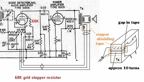
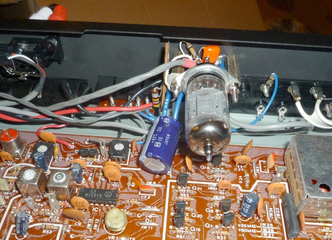
Fig 3: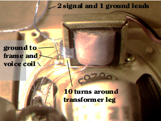
Sometimes an audio amp will present strange behavior. Strange hum behavior is one, interference that seems sensitive to volume control settings or closeness to external objects in an AM radio can sometimes be cured by using a grid stopper. Parasitic supersonic oscillations tend to occur with high gain tubes. Tubes like a 12AX7 or 12AV6. The grid stopper resistor in combination with the Miller capacitance of the tube as seen by the grid works as a low pass filter to prevent the parasitic supersonic oscillation. Guitar amps using 12AX7s often use a 68K resistor connected physically as close as possible (using a short lead) to the grid pin of the tube. This resistor is in series with (the coupling cap and resistor to ground) circuit. An example is seen in the below diagram. The MIller capacitance of a 12AX7 is around 150pF, and this forms a low pass RC filter at around 100KHz.
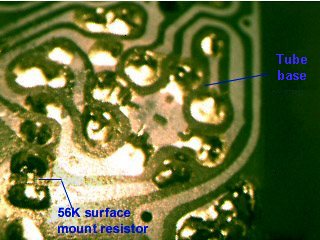
Sometimes a high gain output tube needs a grid stopper. An example I had was that a 60HL5 needed a "grid stopper" resistor of around 4.7K to avoid oscillations at supersonic and RF frequencies. This tube has a high gm. The resistor and the stray capacitances in the tube form a low pass filter that kills gain at frequencies above audio, thus stopping the oscillations. These oscillations can cause audio distortion and can also trash some AM band frequencies. I used a surface mount resistor to bridge across a cut I made in the circuit board trace feeding the 60HL5's control grid. Makes for a neat install.
Fig 1:
Fig 3:
If you have a particularly good sounding AA5 radio with a nice speaker and cabinet (or you could replace the speaker with one intended for car audio), it is possible to add some negative feedback for better fidelity. Some reduction in hum can also be had with negative feedback. There's usually plenty of audio gain avaliable in an AA5 tube radio to allow some use of feedback, as feedback will reduce gain. At first I tried some feedback into the cathode of the 12AV6, but this cathode also serves the diode detector circuit. Oh, it worked, but the feedback ends up being applied to two paths, which, depending on the volume control setting, would tend to cancel out. One solution to this problem is to use a twin triode tube like a 12SL7 or 12AX7, using one section as the triode audio stage with the feedback going into the cathode. Place an additional 56K resistor from the plate to B+ to make the plate load 47K. And use a 2K resistor on the cathode, this cathode resistor bypassed to the voice coil output transformer secondary. Doing this gives us about 2 dB of additional gain, as the plate impedance is lowered. Thus the output tube grid resistor won't load it as much. I used a surface mount resistor on the bottom of the AA5's circuit board. The other triode section is wired as a detector diode, grid to the IF transformer, plate and cathode to ground. See Fig 2 below.
Another method without this drawback is possible. It involves adding a third winding to the audio output transformer. About ten turns around one of the outer legs of the iron core laminations will do. See Fig 1. But as this winding will be carrying the audio input signal, it will need to be shielded from the other windings of the transformer. Use some copper foil tape between this new winding and the other windings of the transformer. And also use some foil tape to shield the windings from the outside world. Ground these shields and the transformer laminations. Be sure not to create a shorted turn around the leg of the iron core. And shield the two leads of this new winding from the transformer back to the 12AV6 circuit. Or if there's enough room in the transformer, you could use very thin coax cable for the new windings. Ground only one end of the shield of the coax. In Fig 3, I didn't need the foil tape. I grounded the transformer laminations and also grounded the voice coil. The voice coil winding (being the outer winding over the primary winding) being grounded acts to shield the new feedback winding from the primary winding. This feedback winding subtracts a little bit of the output signal from the input signal without affecting the detector circuit. That then creates the negative feedback loop. If phased properly, you should be able to short the feedback winding and hear the audio level *increase* a couple of dB, and have less fidelity.
The capacitor usually connected to the plate of the output tube can be reduced to a few hundred pF's, or removed completely. The feedback loop will now keep the radio from sounding shrill.
Which way is the audio transformer phased? We need a negative feedback loop. Phased the wrong way we will get an oscillator instead of an amplifier! If that happens, reverse the leads on the audio output transformer's new winding at the 12AV6 (Fig 1), or the speaker driver winding if you used feedback into the first audio triode's cathode (Fig 2).
For more bass, install a 0.1uF cap from the plate of the triode driver stage to the output tube's control grid. But don't install a bigger cap on the grid of the triode driver to the volume control, as it could back bias the diode detector more, see below.
Fig 2: 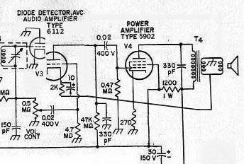
Modulation acceptance is the amplitude modulation percentage (aka modulation index) a receiver's detector can handle without distortion. An ordinary diode detector can handle upward modulation well but detector circuits with capacitive loads have limited ability to faithfully reproduce downward modulation. At some point they clip the audio waveform before getting to zero. Typically an AA5 will start to clip modulation that drops below about 20%. FCC rules say the minimum is about 5%. This level is when the music is at the loudest. The RF carrier varies between 5% and 195% of the "dead air" RF level when the music is loud. This is known as "95% modulation". AA5s tend to clip on modulation above the high 80's.
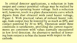
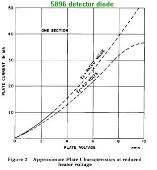
Reduced heater voltage on detector diodes like the 6H6, 6AL5 or 5896
can improve detector performance on weak signals. Less "contact
potential" for the signal to overcome. This should increase the
fidelity of AM detection. The 5896 below is a dual diode version.
This reduced heater trick seems to also work well on 12SQ7's and 12AV6's.
Only thing is to keep in mind that if you reduce the contact potential
for the diodes, it also drops for the triode. But it seems that running
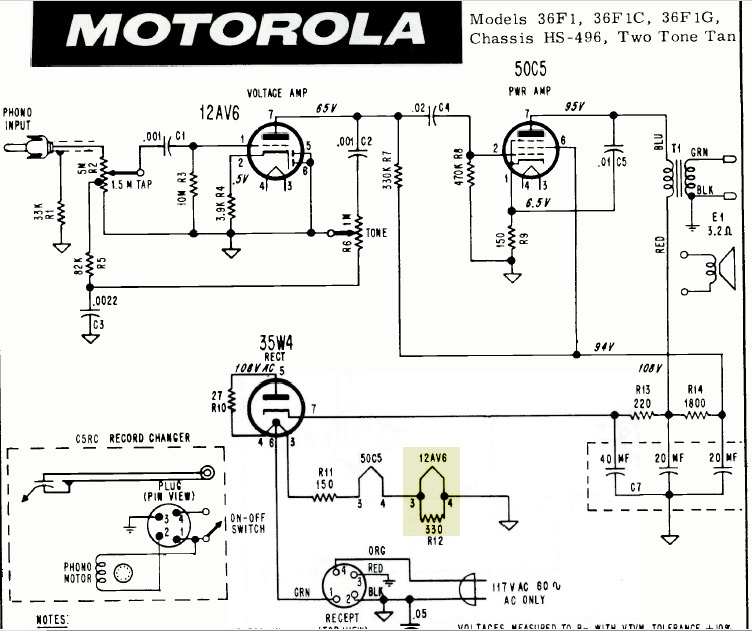
the heater at 10V vs 12.6 seems to be a sweet spot. Parallel a 330 ohm
half watt resistor with the heater in a series string set. If it's a
6SQ7 in a 300ma heater string, use 160 ohms if you have it, or use
150 ohms. For a 18FY6, a 510 ohm resistor would be about right.
It shouldn't hurt the tube, as the current demand on the
triode in an AA5 is quite low. The below graph (original source before edits:
http://www2.famille.ne.jp/~teddy/datalib/heater.htm) shows the impact of
reduced heater voltage on the 12AV6 triode. At 10V heater voltage the
plate current curves are slightly shifted to lower plate currents
vs plate voltage, but not adversely so. Around 9V things start to
fall apart. Below right Motorola did this in an audio amp.
This distortion improvement is due to a better AC/DC load ratio on the detector. The DC load is the resistance directly connected to the detector. The AC load is the DC load with the addition of the resistance on the other side of the coupling cap feeding the grid of the triode.
To avoid "negative peak clipping" you want the AC/DC load ratio to be as close to 1.0 as possible. The further the ratio is from 1.0, the lower the modulation level will be where "negative peak clipping" sets in. The actual negative modulation percentage where negative peak clipping starts is determined by the source impedance of the IF stage driving the detector, and the diode characteristics, as well as the AC/DC load ratio. For comparison a typical "AA5" radio has a DC detector load of 547K and a worst case AC detector load of 433398 Ohms with the Volume control at maximum, for a AC/DC load ratio of 0.792. With the change of the detector load from 500K to 83K (100K in parallel with the 500K pot), the DC load becomes 83K, and the AC load becomes 81K. The resulting AC/DC load ratio of 0.975 is a considerable improvement over the AC/DC load ratio of 0.792 as originally designed. (John Byrns, with edits)
The signal level of each circuit will drop about 6 dB however. You might be able to get some gain back by connecting a small 15pf or so cap from the hot side of the primary to the hot side of the secondary of the IF transformers. This depends on the phasing of the magnetic coupling inside the transformer, however. The antenna circuit's "Q" can also be lowered. In this circuit, one would like an approximately constant bandwidth over the range of the AM MW band. A small resistance in series with the antenna coil before it connects to the tuning capacitor and converter tube will do this. Install a 27 ohm resistor here. After all this, you'll find the radio will only hear the local 50 thousand watt flamethrowers in town. But with better audio response. You can try to boost the gain in the IF stage by bypassing the cathode resistor with a 0.1uF cap to ground. You can use a low voltage cap here, as there will only be a volt or two across it here.
Something to watch out for is 10KHz whistles caused by out of town station carriers if the bandwidth gets too wide.
If you have the typical modern digitally tuned AM/FM stereo receiver
for your home audio system, you probably noticed the poor quality
of the audio from the AM section of the tuner.
No audio high frequencies at all (above about 4KHz). As stated above,
AM stations broadcast audio up to 10KHz. Which makes their AM
modulated signal have 20KHz bandwidth. The FCC assigns carrier
frequencies further apart than this in your particular town. Out of
town signals on adjacent channels are usually too weak to be heard
on your local station.
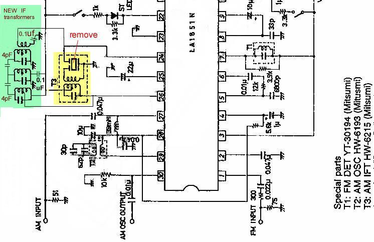
Most modern receivers use a ceramic filter of about 10KHz at most,
yielding audio that tops out at 5KHz. What I did to a set that
uses a Sanyo LA1851N AM/FM stereo chip is remove the AM
ceramic filter and its IF and replace it with a set of 3
IF interstage transformers taken
from
an old narrow band FM pager transistor radio (GE model 4er35a12 if you happen
to have such laying around). See diagram below.
All you need are 3 interstage IF transformers and a pair of 4pF caps.
Here I cut out the section of the old pager circuit board that has these
IF transformers and caps already wired and wired it to the stereo
receiver board where the old ceramic filter and its IF was. You
could do a neater installation than this, but keep the signal wires
as short as practical. 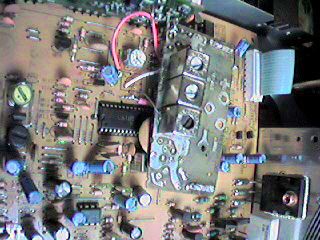
Stations sound much
better now, I get most everything they transmit. This is a
spectral plot of the detected audio from a local AM station. This was
taken from an "S" sound from voice audio. Reasonably flat to
10KHz, the station's transmitter NRSC brickwall low pass filters
to
9. 5KHz as you can see here.
Here's a recording of WABC received thru this wide band circuit. They are usually a talk station, but here they were doing a Xmas music special. Plenty of signal strength at my QTH (had to attenuate it at the antenna to get the distortion down) and plenty of audio highs.
A simulation of the 3 IFs:
And the group delay, which is symmetrical. 20usec differential group
delay has no real impact on the demodulated audio anyway.
 20KHz wide filter
Of course you could just replace the old ceramic filter with one
of wider bandwidth. These tend to be hard to come by.
If the set is digitally tuned, you must select a new filter to be the same IF frequency as the old one. Or else the set won't tune on channel correctly. They come in 450, 455 and 460Khz. If the new filter is off by 10KHz then the set will tune stations one 10KHz channel off, but otherwise sound fine. The tracking across the band will be slightly off. Worse yet is a filter 5Khz off. Then you can never tune the station right.
If the set is analog tuned (ie, slide rule or round dial with twist knob, with an old fashioned tuning cap) the worst that happens is that the dial calibration will be off slightly and tracking off slightly. Most dials aren't this accurate anyway.

I used a pair of 5906 subminiature sharp cutoff pentodes. Triode strapped, but is that significant in cathode follower service? Well, I had lots of 'em, also the 26. 5V heaters makes it easier to run off the SS power amp power supply (+65V and -65V). Also submini tubes are "cute", and small enough to shoehorn inside this receiver. Used the +65V supply with series resistor and with the two tube heaters in series. Okay, but how about B+? Well, I built a kind of voltage trippler circuit with a second bridge rectifier and some "AC coupling" caps. See circuit. I built this on a salvaged small switching power supply board, using its old AC line bridge rectifier and filter cap. This board made a handy way to mount this circuit. The coupling caps went where an inductor filter used to live.
The diagram below shows a simulated amount of power supply ripple (which is the amount I saw with a DVM via a cap after I built the power supply with a dummy load, but before I built the cathode follower circuit), and the tube's power supply rejection on the output. Which is pretty good.
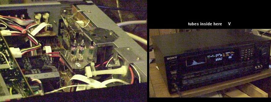
The B+ is just directly rectified off the powerline, making this a hot chassis
radio. But this radio chassis is easily isolated for safety.
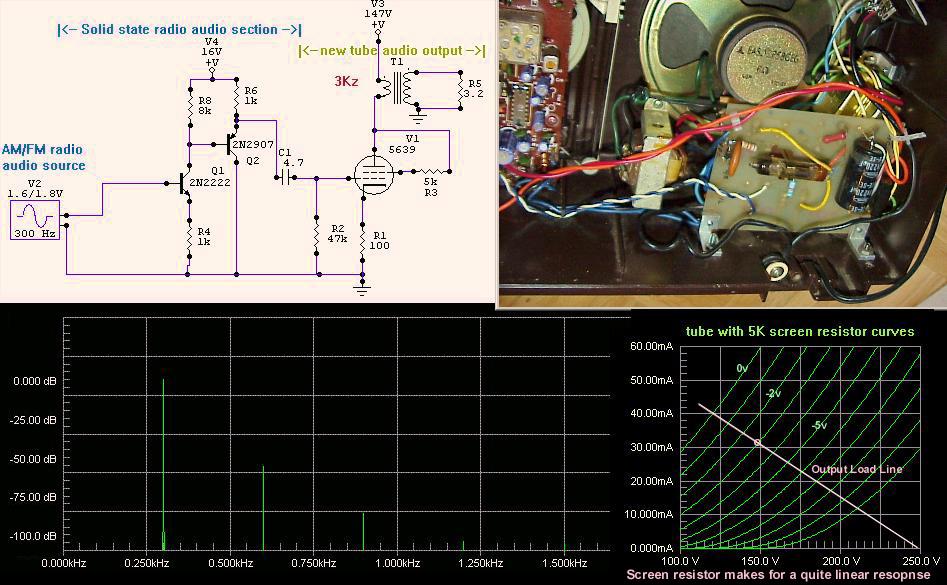
The curves below show the 5639 in pentode mode, standard triode connection mode, and
the modified triode connection, with the 5K resistor between the plate and screen,
and the load taken off the plate and the 5K resistor node. Any load line centered
at 150V and 30ma drawn on the pentode mode curves or the standard triode connection curves
will have rather severe non-linearities. The modified triode mode has
significantly more linearity here.
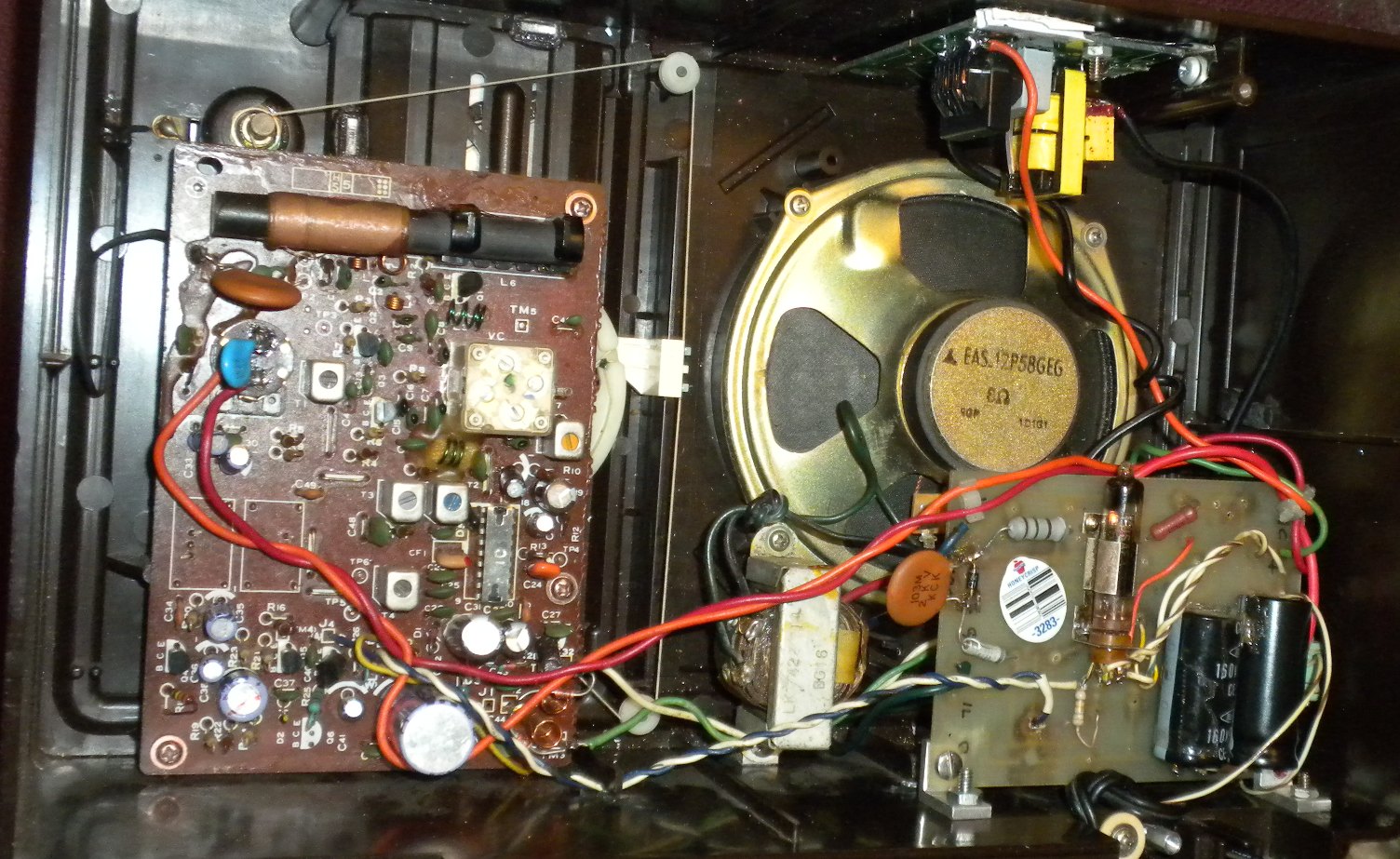 The tube is now in a socket/holder I salvaged from military surplus. The audio output used to be a complementary
pair, but I removed Q6 and replaced it with a 1K resistor. Q7 is now the driver for the tube instead of
driving a speaker along with Q6. C44 was an electroytic, but is now a 1uF poly film. I also changed
several other caps to films, said to be better sounding for audio work. These are highlighted in purple in the schematic
below.
The tube is now in a socket/holder I salvaged from military surplus. The audio output used to be a complementary
pair, but I removed Q6 and replaced it with a 1K resistor. Q7 is now the driver for the tube instead of
driving a speaker along with Q6. C44 was an electroytic, but is now a 1uF poly film. I also changed
several other caps to films, said to be better sounding for audio work. These are highlighted in purple in the schematic
below.
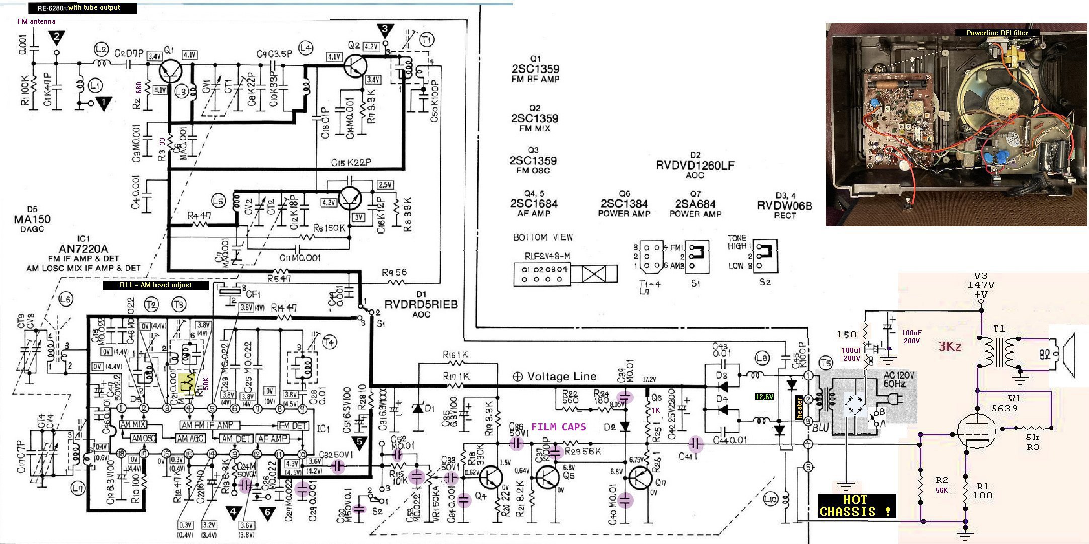
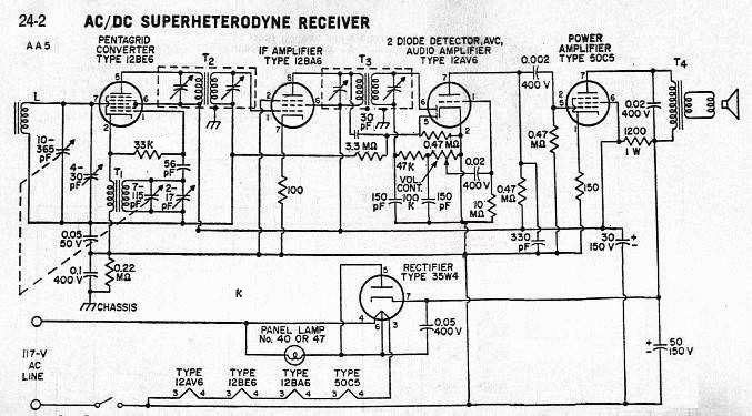
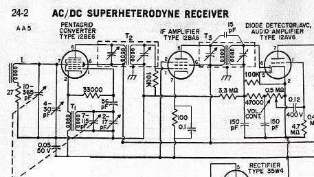
Above is a schematic of this radio, with my mods. Do a "open image in new tab" to see it bigger and better.
I did a number of mods. One as mentioned above was to use a vacuum tube for audio output. A bridge rectifier rectifies the powerline to run the tube. One needs to use a volume control/switch that has a metal partition between the switched powerline and the audio signal in the pot. Else hum can couple into the audio.
Another was to find a way to reduce the gain on AM, so WABC's 50 thousand watt flamethrower located just 6 miles south of me would not distort. Oh, the IC had plenty of gain, but its AGC wasn't agressive enough to reduce gain enough. I ended up introducing some attenuation in the AM IF section with a trimpot of 50K, R11 (R11 used to be a 1K resistor). Listening to WABC I adjusted this pot to get the distortion down, then checked that weak stations didn't get lost due to a lack of enough gain. Usually when using trimpots I can find a wide range of resistance values that work well, in which case I;ll replace the put with a fixed resistor. That wasn't the case here, so the pot stays for now.
Another mod was to increase current thru the FM front end transistor. Lower the resistance of R2 and R3 to about a third their original values. Idea is to give the front end more dynamic range to handle intermod better. Can't really tell if I accomplished that, bu the FM weak signal gain did improve a little.
 .Wonderful tube sound!