The SRF 42 comes apart easily, remove 3 screws from the back (two under the batteries). You don't need to pry off the on/off switch knob, don't try. Radio circuit board will stay with the back. Actually, the back will make a handy package to hold things when you mount it inside your stereo receiver.
Do all these mods in a "non-destructive" process, that is, if things don't turn out satisfactory, you can undo everything neatly and restore everything back the way it was.
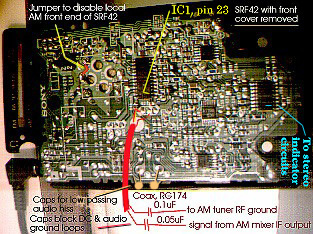
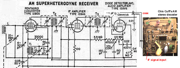
Again looking at the picture, see the red coax (drawn in red) center conductor feeding a node connecting R26 and a ceramic filter. The node on the other side of R26 connects to IC1. The coax ground ties to a local RF ground, the center pin of the ceramic filter is a good point. The impedance of the coax is not a critical number, any thin coax will do. At the other end of the coax, the ground, thru a cap of 0.1uF, ties to your AM receiver's RF ground (a shield can on a coil associated with the AM section will do fine. The cap is to block any DC paths and ground loops that might cause noise on the audio. The center conductor, also thru a cap, this one about 0.05UF (values not critical) connects to a point around the output of the receiver's AM mixer stage, upstream of the receiver's IF amp stage. You will need to poke around with this connection to find a good point to tap. Insert batteries and headphones into the SRF42 and, with the AM receiver's tuning, find a moderately strong AM station, one in stereo would be even better. You may not even need to hardwire this connection, you may pick up enough signal just having an inch or two of insulated wire intermingled with the AM mixer and IF strip circuits.
Leave the receiver's IF strip connected to the receiver's front end, so its automatic gain control feedback circuits will still control the gain of the front end.
If the receiver uses a differing IF frequency, like 455KHz, or 460KHz, the approach would be different: tap off the receiver's IF strip just before its audio demodulator (usually a diode) and thru a DC blocking capacitor, inject it into the SRF42's IC1, pin 23. You'll probably need to cut the trace connecting the SRF42's own 460KHz IF filter to this pin, to avoid messing up the sidebands. You will need good surface mount circuit board handling skills to do this, though. Use coax shielded wire to carry the signal to this point, else you may pick up a strong nearby in town AM station everywhere on the dial. Be sure to use a DC blocking capacitor on the IF's ground, to avoid ground loops and differing DC potentials. You might need to insert some signal attenuation to avoid possible signal overloads into the SRF42's IC1, with a resistive voltage divider or series resistor in line of the above coax. You may find even after this, with the two IF amplifier strips in series, very good reception of distant signals.
Leave the receiver's IF strip connected to the receiver's front end, so its automatic gain control feedback circuits will still control the gain of the front end.
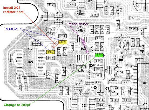
You will probably need to adjust the SRF42's L5, labeled "3.6MHz" to get the stereo to decode properly. Otherwise, you'll get living mono. Mark this adjustment before you adjust it, so you can restore it back if ever desired. This inductor is located on the topside of the board, so you'll need to remove the board from the plastic case to get at it.
Assuming satisfactory success in receiving AM stereo stations with the SRF-42 fed from the receiver's AM front end, you would need to disconnect the old AM section's audio from the receiver's source selector switch, and patch in the stereo audio from the SRF42. Easiest thing to do here is to take the headphone output of the SRF42 and connect it to the switch. You may need to add 1K series resistors to add some impedance, so there will be less "bleedthru" when the switch is selecting another source. You can use the SRF42 volume control to set the level to be compatible with the other audio sources.
If the fidelity of the AM stereo isn't that good as compared to that of the SRF42 when you first got it and before mods, the receiver's AM antenna front end circuit may be picking up more of one sideband than the other. this will cause some distortion. Try loading this LC circuit with a resistor around 10K. This will cut gain, but should help even out the asymmetry of the sidebands.
If the audio seems too hissy, try attaching a pair of caps to low pass the audio some, at the points indicated in the picture. These points are on the back side of the volume control pot. Other end of the caps connect to the silvered outermost circuit board trace. Try 0.05uF. Both caps should be the same value, though.
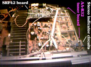
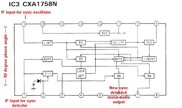
The SRF 42 doesn't provide a "stereo signal being received" indication, just a strong signal indication. A pilot tone at 25Hz is transmitted on the quadature channel, it's about 5 to 10% of full signal strength. This pilot just serves to indicate stereo; it isn't needed to decode the stereo signal (unlike FM stereo, where the pilot IS necessary to decode that stereo). If a true stereo signal indication is desired, one needs to build a 25Hz tone detector. I used a 567 tone decoder chip. To get the signal strength high enough for this chip to sense, I also built a low-pass op-amp circuit designed to pass frequencies below 50Hz. This would help improve the 567's performance, as it won't be hit so hard with regular difference audio.
The stereo difference channel can be found on the SRF42 circuit board on the large chip near the negative battery terminal connection. It's on pin 2 of that chip, right next to the edge of the board. A transistor's base is connected to this pin, to act as a buffer and gain stage. This transistor in turn feeds the low pass op-amp.
The output of the 567 chip can be coupled into the receiver's FM
stereo indicator, in an OR gate logic fashion. You may see the
indicator flicker from time to time, as reception varies. You
probably don't want to use this indication to automatically switch
from stereo to mono, otherwise it will get too choppy. Best to
leave that selection manual. I used the receiver's factory AM
section's output as the mono source, and the SRF42's output as
the stereo selection.
It will take a second or two to achieve stereo lock after you finish tuning in an AM stereo station.
 .
.
 .
.
The Motorola C-QUAM AM stereo system is based on a quadrature modulation (QUAM)
of the AM radio station's carrier. But that's not the entire story. As
most all AM radios use envelope detectors, the quadrature scheme needs to
be modified (C-QUAM) some to make the L+R (mono) signal (which would be the "in
phase" modulation) be detected correctly by an envelope detector
when there is also the difference (L-R) "quadrature phase" modulation present.
Mathematically speaking, the mono (L+R) signal is "multiplied" by
a sine wave at the radio station carrier frequency. To be sure to
get both sidebands AND a carrier, we add "1" to L+R. Else we get
double sideband suppressed carrier, which an envelope detector can't
handle. Add the difference (L-R) in quadrature (multiply by a cosine wave
at the radio station frequency), and an envelope
detector will detect (for a QUAM signal):
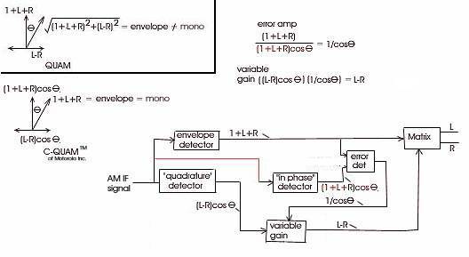
Now, we will have three detectors operating in the receiver: an envelope detector, and
a synchronous system with an "in phase" and "quadrature" detectors.
The envelope detector yields the mono (L+R) signal. We will use this to
compare with the "in phase" detector output to determine what "cos(t)"
is, so we can then divide the "quadrature" output ((L-R)cos(t) to get
just (L-R). After that, we combine the (L+R) and (L-R) signals to
get L and R to feed into the stereo amp and speakers.