Dynaco SCA 35 amplifier modifications
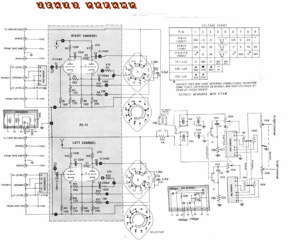
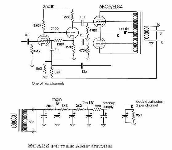
schematics of the stock SCA35 are at the bottom of this page
Idea for getting DC for preamp heaters in the SCA35 amplifier
Thinking of a way to get DC for the 12AX7s in the SCA35 preamp, to reduce heater hum.
By passing cathode current from the output tubes. Yes, the old "preamp tube heaters as
cathode resistors" trick. The four 6BQ5s look to be drawing 147ma of current thru the 95
ohm cathode resistor, to get about 13VDC. That current is close to that used by 12AX7s in 12V mode,
but with 2 12AX7s I'd need 25.2VDC. But I could make that happen if I place a positive bias
(in reference to ground, not the cathode!) on the grid 1's. And do that by grabbing the
voltage between the 2 12AX7 heaters in series (see diagram). That will make the top end of
the 2nd tube's heater be at 25.2VDC, or 12.6V above the grid bias. This is a little like the trick
used to make a 5V regulator chip produce say 9V output (the tube cathode = regulator
output, tube grid = regulator's "ground" pin, which is biased by a resistor voltage divider;
which here are the preamp tubes' heaters). The
actual heater voltage is a tiny bit low, but that
actually helps the linearity of the 12AX7s.
The triode section of the 12AV6 is the same as half a 12AX7
Yeah, that higher
cathode voltage effectively reduces the B+
supply voltage, in terms of the amount of audio output power I can get, but as today's
powerlines are higher than back in the day, that shouldn't be much of an issue.
In addition to giving me DC on the preamp tubes' heaters, this trick should also reduce
the load on the power transformer a little, a little less than 4 watts.
Used some surface mount aluminum electrolytic caps underneath to bypass the heater midpoint
that now feeds the grid resistors on the output tubes. cut the trace to ground, and attach the
cap there. Did this to not introduce crud into the audio.
The preamp has almost no hum (you need the cage in place to shield those ribbon cables), and just
some hiss. Unpacked my turntable and played a few records, sounds fine.
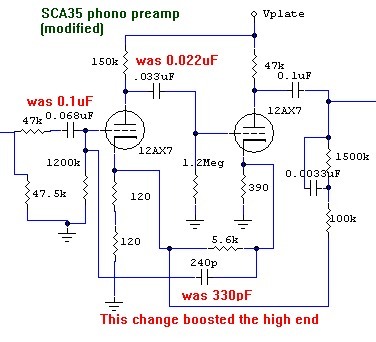
Mod to bring up the highs in the phono preamp
I have a RIAA test record "FEWR-A" from BSR Electronics. "For use with models FEW II, III and IV" but it
shouldn't matter what turntable you play it on, to feed my SCA35's phono preamp.
Oh, and regular music LPs sounded good after I was done with the tests and mod.
 Before these results and my modification, I noticed that the phono preamp seemed weak on the highs,
so after I figured out the phono preamp schematic (making sense of those switches was a bit of
a PITA) I simulated it, and it did come out a little low on the high end. Played with various
component values, but the only one that did what I needed was to change the 330pF cap to a smaller
value, 240pF. Which looks to get me closer to a proper RIAA curve, as seen in my results
measuring the waveforms off the test record. (The tone controls were centered, as they might
affect the "tape output" jack some).
Before these results and my modification, I noticed that the phono preamp seemed weak on the highs,
so after I figured out the phono preamp schematic (making sense of those switches was a bit of
a PITA) I simulated it, and it did come out a little low on the high end. Played with various
component values, but the only one that did what I needed was to change the 330pF cap to a smaller
value, 240pF. Which looks to get me closer to a proper RIAA curve, as seen in my results
measuring the waveforms off the test record. (The tone controls were centered, as they might
affect the "tape output" jack some).
 Yummy!
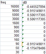
And using an o'scope to measure the "tape output" jack's audio signal (after doing the mod),
I tabulated this table (normalized at 900Hz) with excel. The only mod that made a difference in
the curve was the 240pF cap. With the original 330pF cap, the high end was down about 3dB.
Which my ears noticed. The other two caps look to be coupling caps only, and as I was replacing
the 0.1 ceramic disc  and the Dynaco light blue cap 0.022uF with WIMA MKP10's (Polypropylene,
which IIRC should be a good choice for audio work) in 0.068uF and 0.033, which I had lots of, and I
was out of 0.1uF's and no 0.022uF's on hand. Simulation
showed that these didn't matter, and my tests and ears seem to verify that.
and the Dynaco light blue cap 0.022uF with WIMA MKP10's (Polypropylene,
which IIRC should be a good choice for audio work) in 0.068uF and 0.033, which I had lots of, and I
was out of 0.1uF's and no 0.022uF's on hand. Simulation
showed that these didn't matter, and my tests and ears seem to verify that.
SCA35 mod: convert that "tape head" input to line level
What I did was change the function of the "Tape Head" input from a low
level phono like
input to a line level input. Biggest pain was figuring out a way around
the oddball switching
arrangement of the selector switch. Eventually figured out a way, which
was to use the phono-tapehead
equalization portion of the switch to do a preselect of phono or the new
line level "tape head"
(I stuck with calling it by its old name, as changing the silkscreening
on the front and rear panels would
be a bit difficult and make it look neat). The
equalization RC (the 1. 5 meg resistor and 3. 3nF cap) was moved to the
circuit board and hardwired into the now RIAA only phono preamp.
To avoid crosstalk from unselected inputs, I kept the "short 'em to
ground" scheme. Also note I hard
wired the preamp tube input to point 17, instead of making it go thru
the switch like it used to. But
I kept the switch connection on point 17, so the short to ground when
unselected would still happen.
And the wire in the phono and tape head input braid that used to connect
to the "tape head" RCA jack I
tied to ground (as additional shielding for the phono input line). I ran
new shielded cable from the
old RCA tape head jack to the above new line level switching.
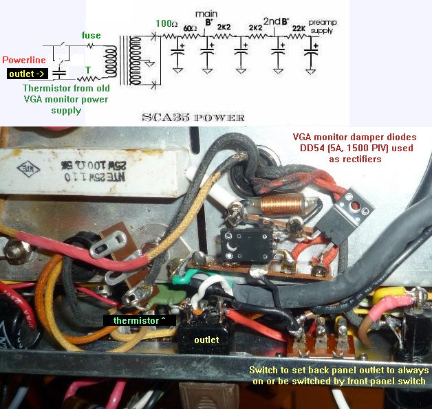
Inserting an inrush current limiting thermistor on powerline side of power transformer
Here I did a few simple things. Main one was to add, on the primary
side of the power transformer, a thermistor
of the sort found in old PC power supplies and VGA monitors. The one
that feeds their internal power supply circuits
(primary side rectifier and filter caps), not the degaussing coil.
These are usually about 15 ohms cold, and when they warm up the
resistance drops to
around 3 to 5 ohms. They look like disc ceramic caps. The one I used
is colored green, they are commonly
black. This limits inrush curent when you turn the amplifier on.
Inrush from cold tube heaters, and from initial
filter cap charging.
Another thing I did, was to replace the old silicon rectifier diodes with damper diodes that are rated 1500 PIV and average
current of max 5A and max peak 20A. I had these on hand: I doubt that the currents will come close to the specified max
values. The coil has no real purpose other than to act as a jumper wire between the diodes and the 100 ohm resistor
I used to drop the B+ a few tens of volts (the 6BQ5s I was using got unhappy with the B+ a shaded too
high (higher powerline voltage today), but now I have 7189s in this amp now). Left this resistor in as I won't miss
a watt or two of peak audio output power, and not work the tubes so hard.
A third thing I also did was to figure out what to do with the chassis hole created when the unswitched
back panel outlet broke apart. No suitable outlets avaliable, so I did a rather lame modification: Use a switch to
select the mode the other back panel outlet will be in, switched by the front panel power switch, or be always on.
Yes, a stupid feature, but I wanted to fill the empty hole in a way that looks like it has a purpose.
Diagrams of the stock SCA35: