
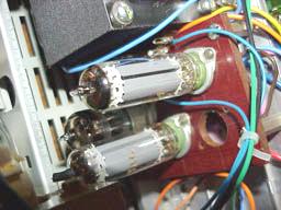
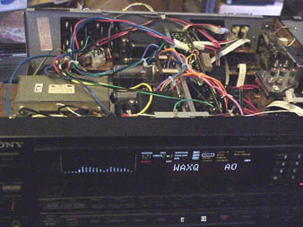
This receiver already has a big honkin' plus 65V and a minus 65V power supply, from a big centertapped power transformer. Easy enough to tie the negative supply rail to ground, and the positive side now becomes 130V. other parts of this receiver has their own transformer secondaries and thus independent power supplies, aside that the florescent display wants the +65V. So I moved that from the positive supply to the CT, which now looks like +65V. Changed the big filter caps, as the OEM ones didn't look so great (bulges on their tops). Now they are 1000uF for each portion of the bridge to center tap. Drop the new 130VDC thru a 130 ohm resistor and another filter cap to filter out hum. So what tubes to use? Well, there's no high current low voltage secondary on this transformer, and no real room for a filament transformer. But if I go for low audio power, around 1-1/4 WPC, some options open up. I have lots of 50C5s from my AM tube radio sub-hobby, and combined with a 12AT7 twin triode, makes for 112V worth of heaters, in series. All these tubes have the same heater current, 150ma. So that matches up well with the 130V (add a dropping resistor to drop the 130V to 112V). Okay, I need a pair of output transformers. Check the web, Most only single ended OTs are either too big to physically fit or have no bass. I did find good ones that would fit and have bass, though at lower but enough power, on that auction site everyone knows. A pair of OPTs made by Transcendar Transformer co, model TT-10-OT.
They spec out as (copied from the auction listing):
3k Audio Output Transformers for SE amp, 8 ohm
output transformers for a Single Ended Tube Amp.
"These are high quality, excellent sounding Audio Transformers". Made in USA
These transformers may be used for single ended amplifiers with a variety of tubes including
but not limited to 300B, 2A3, 6A3, 6B4G, 6L6, 807, 5881, 6550, 6V6, EL84, and 6AQ5
The smaller size of these transformers along with the single 8 ohm secondary tap allows for
extended high frequency range.
Frequency response is 20 Hz to 100 kHz ±1 db at 1 watt, tested on Hewlett Packard audio analyzer.
Each transformer has the insulation Hipot tested to 3000 Volts DC.
Constructed with high grade M6 grain oriented silicon steel laminations for excellent
low frequency response and low distortion.
Primary and secondary interleaved for excellent high frequency response.
Core has an air gap for single ended operation.
Primary impedance is 3000 Ohm (3K) , Primary current 100 mA, DC resistance is 300 ohms, 20 Henrys
Secondary is 8 ohms and is conservatively rated for 10 watts continuous.
Lead wires are 18 gauge Teflon insulated, type E, with silver plated copper conductor.
Overall dimensions for each transformer is 3-7/8" x 3" x 2-1/2" tall
Each transformer weighs 4 pounds.
Below is the schematic diagram:
The 50C5 is a tube commonly used in old AM tube table radios. Its
load resistance is rated as 2.5K. The 3K OPT if the speaker load is 8 ohm.
The "dummy load" 47 ohm resistor (connected inside the amp, to reduce the
possibility of damage due to no load on the amp) would reduce that a little.
The left-over mismatch is not at all critical, and can be ignored. The 12AT7 driver
is just a typical circuit pulled from the tables in the back of the
RCA tube manual. No feedback other than that you'd get from an unbypassed
cathode resistor on the output tube. The amp has about -42dB of 2nd harmonic, and the
3rd is down at about 72dB, as you can see in this below plot:
Plotting the frequency response was a little difficult in that I had to "fake it" with one computer with cooledit playing a linear frequency chirp feeding the amp, and a 2nd computer capturing with cooledit the speaker output. Ended up with linear/linear plots, where I'd prefer log/log plots. But I did it with 3 passes, all starting at 20Hz, and one ending at 200Hz, another at 2KHz, and the 3rd ending at 20KHz. The X axis is a linear plot of output voltage seen across the speakers. The speakers are 3 ways, made by "Audio Electronics Systems" model 310. Yeah, not one of your famous makes. Mentioned as speakers are not usually even with respect to frequency loading, so some of that will show up in these plots. And on the off chance that some of you might know these speakers, but I doubt it. As it is, the plots (via eyeball estimate) show that it deviates about ±2.5 dB from flatness from 20Hz to about 17KHz.
Now into just an 8 ohm resistor (no strange bumps, just smooth ones, now about ±1.7dB from flatness.
This is a little higher than the claimed flatness of the
transformers themselves, but this is probably due to the above mentioned 2.5K - 3K plate load mismatch.):
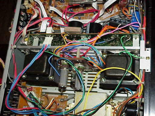
What it looks like inside (I used an old thick piece of "glass-phonolic" board
as the amp "chassis", usual point-to-point wiring used underneath):
 -->
-->