

Infinite impedance detector for higher AM reception fidelity>] : : : |-
to >] : : : |-
A solid state radio modified with a filament tube detector
Using a base-collector strapped transistor as AM detector, sharper knee for better weak signal demodulation
An AA4 modified with a radio IC for better reception
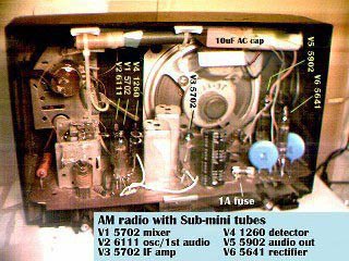
What if a subminiature version of the "All American 5" tube AM radio had been developed and produced? I modified a few common circuit board based AA5's replacing the regular tubes with sub-mini's.
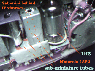
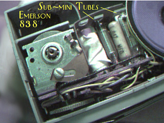 Production AM portable radios using
sub-miniature tubes were made by Emerson and Motorola. AFAIK, no production
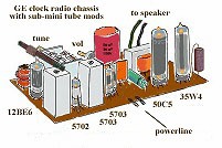
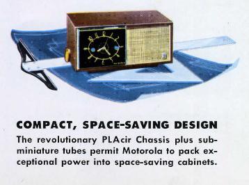
AM table radios were made using sub-mini's. The image above right, from a Motorola 1955 brochure, implies that
submini tubes were used in their clock radios, but I don't think that actually happened.
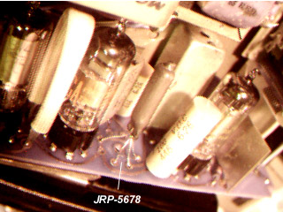 First an easy substitution: A JRP-5678 filament tube in place of a
1U4 filament tube in a portable radio. Note that a 47K resistor
needs to be inserted between the 1U4 pin 3 and the 5678 pin 2,
also a 0.01uF cap needs to be connected between the 5678's pins
2 and 3. This is to reduce the screen voltage from 90V to 67V, and
to bypass the screen to the filament for an RF ground.
First an easy substitution: A JRP-5678 filament tube in place of a
1U4 filament tube in a portable radio. Note that a 47K resistor
needs to be inserted between the 1U4 pin 3 and the 5678 pin 2,
also a 0.01uF cap needs to be connected between the 5678's pins
2 and 3. This is to reduce the screen voltage from 90V to 67V, and
to bypass the screen to the filament for an RF ground.1U4 pin 5678 pin 1 3---\ 2 1 0.01uF 3--47k--2---/ 4 nc 5 3 6 4 7 5
That's right, the 5678 pin 3 connects to both the 1U4's pin
1 and 5. Also note that the filament DC supply should have pin 3 of
the 5678 more negative than its pin 5. The control grid is built
expecting this. Same is true of the 1U4, its pin 7 should be the more positive
filament pin. An alternative method of bypassing the screen grid
is to connect a 0.1uF low voltage cap in parallel with the 47K resistor instead
of the 0.01uF cap to pin 3 of the 5678. This alternative bypasses the
screen grid to B+, which should be a good RF "ground".
You shouldn't need to touch the alignment of the IF strip.
Data
on the 5678.
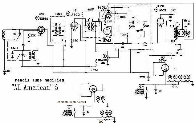
I modified 3 "AA5" AM tube radios that were built using circuit boards. Before doing anything else, verify that the radio is fully functional, decent reception, low/no hum or distortion. Fix any problems before attempting these mods! The first one, a GE clock radio from the early 60's, I removed the 12BA6 remote cutoff pentode IF amp tube and the socket (use solder wick, these circuit boards can't take much abuse) and installed a 5702 sub-mini remote cutoff pentode tube. The sub-mini usually comes with wire leads about 2 inches (5 cm) long, and you can bend somewhat the leads to form a pattern such that it duplicates the same functional pinout as the 12BA6 (cathode=cathode, g1=g1, etc). If there is no cathode resistor, add a 180 ohm resistor, otherwise replace the existing one with a 180 ohm resistor. Tube will probably oscillate some with values lower. Also, IMPORTANT This tube needs an external grounded shield. Otherwise, it will oscillate on you. The 12BA6 has one built in, but the sub-mini's don't. Any convenient solderable metal formed into a round shield will do, you only need cover the portion of the tube where the plate lives. That way, you can still see the top of the tube's glass bulb, and also more importantly, avoid shorting to the wire leads. Solder a wire to the shield, and connect it to RF ground in the local area. I used a piece of wire stiff enough to hold the shield mechanically in position. Now, it's time to test it. Yes, I realize that the heater current of the 5702 is 200ma, and the rest of the radio is 150ma, but it will work well enough to verify things at this time. You may want to use a variac and bring the line voltage up slowly with the radio on. Check to see all the tubes are glowing at reasonable levels, note that the sub-mini will be a bit brighter at first. but should settle down in a few seconds. Radio should start playing, tune around the dial. If not, check the wiring you did.
Assuming success so far, we now turn our attention to the 12AV6 detector/avc/first audio tube. We will use two 5703 triode tubes here, one will be the detector and AVC tube, the other will be the first audio amp triode. A triode for a diode function? Yes, the cathode will be tied to ground, and the grid tied to the IF transformer output. And the plate will be used as an internal shield, tie it to ground. And the first audio amp triode's cathode goes to ground, like the 12AV6's did, and grid to grid, plate to plate. If the fidelity of the audio amp triode is too distorted, inserting a 22K ohm resistor (value not critical) between the cathode and ground may help. Better fidelity can be had if some negative feedback from the speaker winding of the output transformer is applied to this cathode resistor. This is now possible now that the diode detector cathode and the first audio amp cathode are separate. Be sure to pay attention to the routing of the heater currents (the 12AV6 usually is at the signal and power ground of the series string heater circuit, and one of its heater pins is grounded. To avoid introducing hum into the audio, use the same physical location to ground the detector/AVC 5703 tube heater as used by the 12AV6 heater. Or else you may get ground loop problems. The circuit board designer back when went to some effort to avoid ground loop problems. Connect the other end of this tube's heater to one of the other 5703 triode heaters, and the other heater of that tube goes to the other heater connection the 12AV6 used. According to the RCA Tube Manual, the preferred order of the series string heater order is to have the detector tube at ground, than the first audio triode, then the IF, etc. Test the radio bringing up the variac with the radio on. Should work, if not, check the wiring.
Assuming again success, we now address the heater current difference. In my radio, the detector/AVC tube, then the first audio tube, then the IF tube were wired in series. Then came the 12BE6, the 50C5 and then 35W4. To provide the new tubes an extra 50ma of heater current (to bring it up from 150ma to 200ma) add at the IF tube - 12BE6 heater node a 2K 10W resistor and the other end of the resistor to the top of the heater string, at the power input node. (The other side of the power line, the one not connected to the radio's system ground (probably thru the power switch)). If the radio had the 12BE6 heater between the IF tube and the first audio and detector tube(s), you'll need to wire in parallel a 250 ohm 1W resistor across the 12BE6 heater, and attach the above 2K resistor to the new IF tube - 50C5 node. Test it again, carefully measure the AC volts on the heaters of the new tubes to see that they are at reasonable values (±10% is fine). And the radio should still work!
Another way to power the 200ma heaters would be to insert them between the radio's ground and the incoming powerline (usually thru the power switch). Thus the heater string pulls its current thru the submini tubes with the 200ma current rating. When the rectifier tube and other tubes are warm enough to conduct current thru their cathodes, this current will add with the heater string current to pass thru the submini tube heaters. At this point this current is not a constant DC, but it consists of filter capacitor charge pulses. But the heaters are essentially pure resistances once up to temperature and it doesn't matter. But you'd need a true RMS meter to measure it correctly. You may need a resistor of around 100 ohms across each submini tube as the added current will be a little too much. With a suitable resistor in parallel, this technique can heat any tube where the heater current is between 150ma to 260ma. Keep in mind that this will reduce the radio's B+ supply voltage.
One could use a capacitor instead of the resistor to provide the extra current thru the heaters of the new tubes. Realize that the current thru the cap will be "imaginary" (I hated this term in math class, to me, "imaginary" meant "fake"). The 150ma of current thru the other AA5 tubes would be "real". We need to do vectors here, to get a final result of 200ma thru the new tubes. Doing the trig yields about 130ma of imaginary current, and approx size 3.3uF 250VAC cap will provide this. One could do "S" parameters to solve this problem as well, just like back in ECE232 class at Syracuse University in 1976.
Schematic of the above described radio:
First thing to do is get a second AM radio (any type, need not be a tube radio) and tube in a weak station above 1000KHz. And turn on the radio you're doing the mods to, and after you verify that it receives stations, tune to a spot on the dial 455 KHz lower than the weak station being received on the other radio. With the two radios about 2 feet apart, you should hear a heterodyne whistle "jamming" the weak station on the non-mod radio. You are hearing the mod radio's local oscillator leaking out into the air. Normal. European governments used this trick to hunt for people who didn't pay some sort of "radio tax" or something. Anyway... If possible, leave the socket in place, and attach the tube wiring on the bottom (foil side) of the board, using the tube socket solder nodes as places to solder. If the following is successful, you can rewire things to live on the top side of the board. If it's not satisfactory, remove the attempt and reinstall the 12BE6. On this optimistic note, let's continue: Using a 6111 twin triode, connect the cathode to the cathode pin of the 12BE6 socket, grid to G1 pin, and plate to the g2,g4 pin (which should be the local B+ line). The mu (20) of the 6111 tube is the same as the mu (20) of the oscillator portion of a 12BE6 (cathode, g1 and g2 (which corresponds to the plate of the 6111)). No mods to the oscillator coil or cap are needed. (The other section of the twin triode will be the first audio amp. Better sound was had by using a 2K ohm resistor in the cathode circuit of this audio stage, and paralleling a 56K resistor across the plate resistor of 470K). Connect the heaters to the heater pins. Fire the radio up, and with the other radio tuned to that weak station, tune around the dial on the mod radio, and if the triode tube is working, you should hear the local oscillator. You won't hear any stations on the mod radio now, next thing is to add a mixer tube.
First method:
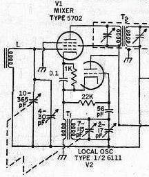 (On the
left is a portion of the below circuit diagram, featuring the cathode osc
injection)
Using a 5702 pentode, connect its plate to the 12BE6 plate pin, its grid 1 to pin 7 (g3) of the 12BE6 socket, g2 to B+, and connect g3 and the cathode of the 5702 pentode together, and to a 68 ohm resistor and a 0.1 or so cap. The other ends of these resistor and cap connect to the cathode pin of the 12BE6 socket. And insert in series the heater. Now fire up the radio again, see if you hear any stations (may be weak), and also see if the other radio can still hear the local oscillator. You may need to adjust the value of the 1K ohm resistor above to get better results in signal strength. This is very similar to the mixer in the radio built using compactron tubes and should work fine. As mentioned before, you may have more difficulty here than with the previous IF , detector and 1st audio tube mods. You can always go back to using the 12BE6. Don't twiddle with the alignment too much, it would only have impact on the upper end of the band. The lower end of the band doesn't much notice small differences in capacitance, and the above mod would only affect capacitance, and not inductance.
An alternative mixer circuit
using screen grid local osc injection:
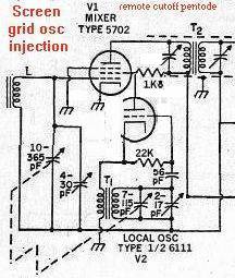 (On the
left is a portion of the below circuit diagram, featuring the screen grid
osc injection)
Instead of injecting the local osc into the cathode of the mixer tube, inject it into the screen grid (G2). Insert a 1K8 (1800 ohms, Europeans use the "K" in place of the decimal point "." to improve readability, as the "." is small and can get lost in the dust. 1K8 -> 1.8 * 1000 -> 1800, 1000 for the "K") resistor between G2 and B+, and connect the plate of the local osc triode here. And instead of the mixer cathode resistor described above, connect the cathode to ground. And remove the cap between this cathode and the local oscillator tube cathode! A downside is that a strong station may "pull" the local oscillator. A larger value of this new resistor will make this happen more, make it too small and the conversion gm will drop, making sensitivity go down. As the transconductance of screen grids is pretty low, this method won't have much gain. The mixer tube is acting as a multiplier, make the local oscillator amplitude smaller (smaller value resistor in osc plate circuit) and the signal being the same strength, will yield a lower amplitude product (IF signal at 455KHz). Be aware that a larger amplitude osc signal on the osc tube plate will cause some "Miller effect" (like you get in transistors) and shift the osc frequency a little (this is separate from the above mentioned "pulling"). This is the least satisfactory of these three methods, and is mentioned as an introduction to the next below method, which uses a specially designed G3 instead of G2.
Yet another alternative mixer
circuit using a dual control pentode:
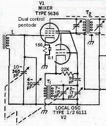 (On the
left is a portion of the below circuit diagram, featuring the dual control
pentode used as a mixer)
Here a dual control pentode (5636) is used as a mixer. A dual control pentode has two control grids, G1 and G3. What would be the suppresser grid is the second control grid. This grid is connected to the oscillator grid, and thus it "chops" the signal from the antenna (applied to the first control grid). This causes heterodyning mixing action to occur. This circuit has more conversion gain (the 5636 is rated to have a conversion transconductance of 1280 umhos) than the above screen grid injection, and the oscillator has less amount of "pulling" from strong stations. Be sure to add an additional 120 ohm resistor in parallel with the heater, as the 5636 draws 50ma less heater current than the 5702.
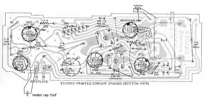
I then went on to the 50C5 audio output tube and the 35W4 rectifier tube. I used a 5902 beam power sub-mini for the audio output stage. Its rated load is 3000 ohms for 1 watt, vs. 2500 ohms and 1.9watts for the 50C5. Close enough load specs, the slight difference will mean slightly less output power. At this point, it's a direct pin for pin function substitution except for the heaters, and the cathode resistor changes to 270 ohm. And I used a 5641 rectifier to substitute for the 35W4. An 18 ohm resistor in series with the cathode limits the peak capacitor charging currents to below this rectifier's peak current rating of 200ma.
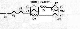
At this point, I rearranged the series string heater arrangement. Using a 10uF AC capacitor, rated for 200V at 60 Hz (1.4KVDC), to drop the power line voltage down to 24V at 450ma AC, provides the heater power. This first feeds into the rectifier tube, which consumes all 450ma, at 6.3V. Then this in turn feeds in series into the audio tube, which also takes all the current at another 6.3V. At this point, the rest of the tubes consume less heater current, so a series/parallel arrangement is used. The pentode tubes (mixer and IF) consume 150ma and 200ma each respectively, or 350ma when wired in parallel. Add a 60 ohm resistor in parallel to make it 450ma. Or use a pair of pilot light bulbs, 6V @ 25 ma each, (Radio Shack has 'em) wired in parallel with the 5636 and 5702 heaters and a 120 ohm resistor. These heaters, along with the capacitor, will limit the current and voltage the bulbs will see. And this configuration then feeds into the 6111 twin triode (300ma), and in parallel, the diode detector tube (150ma), for a total of 450ma. These two last tubes' heaters then connect to ground. I had first used a transformer to power the heaters, but it was rather big. One could easily imagine a higher heater voltage sub-mini beam power and rectifier tubes, but aside from the 7762 pentode (same as the 5902 except for a 26.5V@110ma heater) none were actually made. I haven't been able to find any 7762s, maybe they were just "vaporware". Data sheets in pdf form: 5636, 5641, 5647 (similar to the 1260), 5702, 5703, 5902, 6111, 6BA6, 6BE6.
 Here the above pilot lights are lighting
the radio dials in the dark.
Final Schematic using the first method:
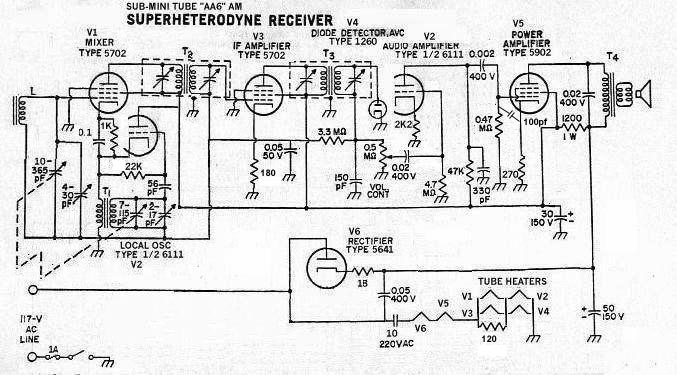
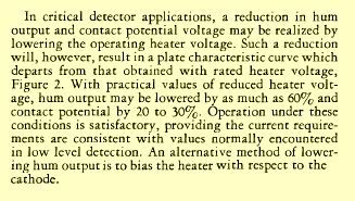
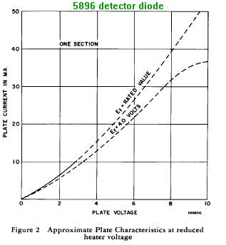
When using a separate diode, like an EA76 or 5647, better detector fidelity
can be had by reducing its contact potential. You can reduce the
contact potential by reducing the heater voltage down from 6.3 to
4 volts. In a series string, that can be done by paralleling a
100 ohm resistor with the heater. In this series/parallel set, an extra
15 ohm resistor is used. This should increase the
fidelity of AM detection. The 5896 below is a dual diode version.
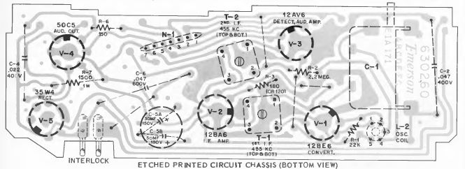
This circuit board diagram shows the original:
and the mods using the "first method" of
the mixer circuit:
 .
.
This completes the sub-mini tube AM radio. Aside for the 12BE6, is was pretty much a simple substitution of tubes. The third radio below replaces the 12BE6 with another miniature pentagrid converter tube, the 6BA7. This tube has 6dB more conversion gain.
Data sheets with curves can be found in PDF form for most of these tubes at: Frank's web page. Be aware that there is a daily download limit of about 4 megs at these sites.
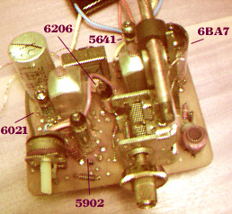
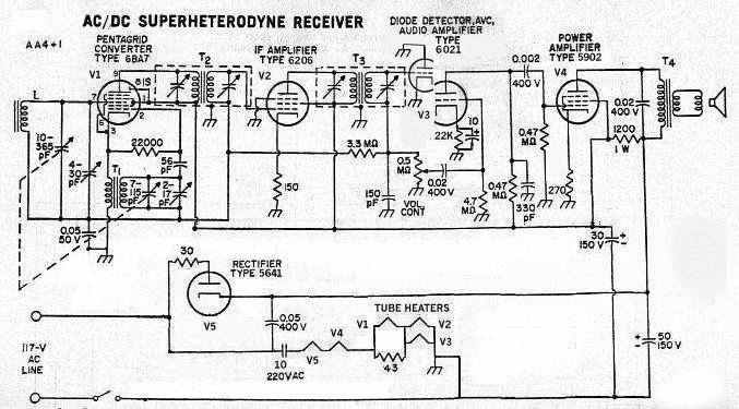
Yet another AA5 (an Emerson 708B) modified with some subminis and designed to run off 8VAC. Why 8V you ask?
This dates back to my late 1960's model railroad days when I ran HO scale streetlamps off 8V instead of 14VAC,
to prolong bulb life and make the lamps look more realistic. Built a 8VAC 5 amp bus for this. Still have it. Anyway:
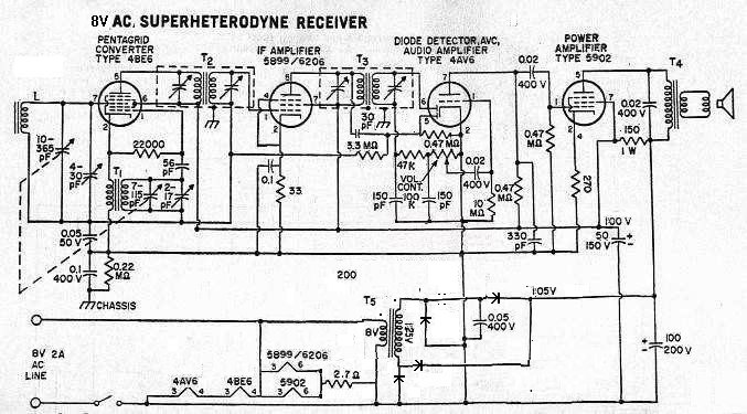
To get plate voltage I used a 110V to 16V centertapped transformer run in reverse 8V to 110V. Often, you
can do surgery on the transformer to get at the magnet wire connections to the wire leads leaving the
transformer. One can usually get at these connections, and split the two magnet wires off the centertapped
lead. And then take the resulting 8V windings and put them in parallel, carefully to get the
phasing correct!.
The nature of the current filter cap recharge is
that it looks like pulses with a duty cycle of around 5%. This radio's current draw on the B+ is about 40ma, and
this combined with this 5% duty cycle makes for peak currents 20 times larger, here about 0.8A. And with
the 110V secondary resistance of about 32 ohms that makes a loss of 25VAC. Subtract 25V off the 110V and
that yields 85VAC, and with the bridge rectifier (1.4 times the AC) that produces 114VDC. About what I measured. Secondary resistance
is effectively multiplied, making it worse than you'd think.
You don't see this with hot chassis silicon diode
rectifier power supplies, as American 120V 15A branch circuits have an effective resistance of about
1⁄3 Ω.
Suprisingly, this radio picked up (weakly) WFBL Syracuse here in northeast New Jersey. Propagation must have
been good. 
What it looks like: 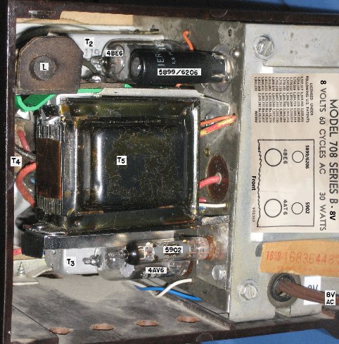 I edited the tube placement chart, printed it out and glued it to the cabinet bottom. It's here as an insert
in this picture.
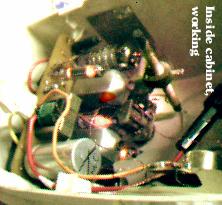
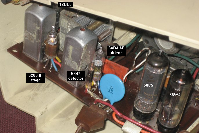
Here's a pretty common GE plastic AA5 clock radio, the C435A modified with a 6026 submini semiremote
cutoff pentode for the IF stage, and a 5647 detector diode, and a 6AD4 triode for the audio
driver in place of the 12AV6. I initially tried to gather all the tubes in one cluster (using
subminis for the IF and audio driver and detector), to simulate a single tube "AA5"
"Single tube "AA5" radio, what if?" as described in my web page , but the IF
stage is rather fussy about unintended feedback. So I reworked this radio to place the tubes in
their original locations, but substituting with the same subminis as mentioned.
Turns out the submin heaters consume a bit less current than their ratings state (150ma, seems they actually use about 130ma), so I added a 1K shunt to get the heater voltage more correct on the subminis.
The radio works quite well. It didn't work so hot with the tubes grouped together (the IF oscillated). Oddly enough, initially I forgot to install the AVC filter cap, and the radio worked, but was insensitive. Added that cap and got tons of motorboating. I then placed the same tubes in their original positions, no circuit changes other than that, and the radio works well.
For some extra grins, I changed the 22K resistor at the 12BE6 to a surface mount resistor I pulled off an old computer motherboard. It went right between the circuit board lands holding the tube socket.
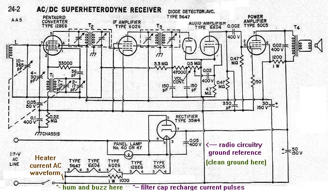
Another thing worth mentioning is that the diode's heater is placed right at the ground end of the heater string, and I connected it via a wire jumper (that's the white with brown spots wire in the picture) to the point on the board where the switched powerline wire comes in. Idea is to avoid any AC heater currents from flowing thru the board grounds, to avoid hum inducing ground loops. This incoming point is where I also connected the negative end of the first filter cap, to also keep cap recharge pulses from inducing buzz into the board grounds. The "radio circuitry ground reference". as commented in the above schematic.
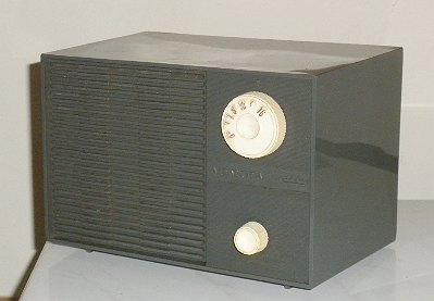
Had an Admiral AA4 radio, the kind that used an autodyne 12AU6 converter, no IF stage, and the usual 12AV6 50C5 and 35W4 circuits. It was insensitive, and it had a boring plastic cabinet anyway. So I did a "restormod" (restore and modify) on it. Usually frowned upon, but if the original electronics are too far gone, or boring...
At a garage sale picked up a Sony AM-FM "transistor" radio that had a beat up cabinet. I figured I could use this radio's circuit board to replace the RF sections of the above AA4.
In step stages, I removed the FM specific parts from the SS board,
making it AM only. Tested it to see if
I broke something. Removed its tuning cap and measured it with a cap
measurer. The antenna was 150uF
max, and the osc 100uF max. The AA4's original tuning cap is antenna
400uF max and osc 100 uF max.
This means I can use the SS board's osc coil, but tring to match the
antenna tuning cap to the SS
antenna needs work. Never did get satisfactory results, but I then
decided I could make use of the
AA4's loop antenna, and install a tap to feed the SS chip's AM antenna
input. Looked at the data sheet
of the chip, a CXA1019S and it had a spec for the AM antenna listing the
number of turns for the LC
circuit and turns for a secondary to feed the chip. Which gave me a
turns ratio that I can then pick a
point on the loop antenna to install a tap, ideally 22% but here at 20%,
close enough. And this allowed me to keep the original loop
and tuning cap to preserve the original antenna LC circuit. The osc
tuning cap was very close, and the
SS osc coil is adjustable, so mating the original tuning cap to the SS
osc coil was no problem.
Tested it at this point, to see if any mistakes happened, and to tune
things up.
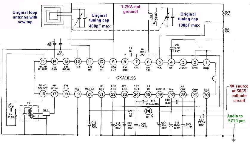
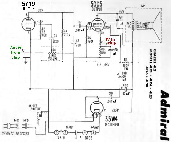
With this success, now it's time to merge this above chip to the audio driver (changed it to a 5719 submini tube, you may need to lower its plate resistor, I used a surface mount resistor in parallel to get it to 270K), output and rectifier tube circuits. Need a 4V power supply for the chip, which I can get from the 50C5 cathode circuit. This cathode runs around 6V, so I used a resistor voltage divider to get the 4V. And this divider lets me use a cap to filter the 4V to remove cathode follower induced audio. But still letting me have some cathode follower feedback for the 50C5. The chip's speaker output now feeds the AA4's volume control. The "transistor" radio's volume control I set to give me a reasonable level of audio to feed the AA4's pot, selecting a undistorted audio level, aka "line level" that you'd get from the old tube AM detector circuit. Used fixed resistors to replace its old volume pot, once I determined the setting of it.
Used an AC voltage dropping cap (here a 5uF 220VAC rated) to drop the missing 30 volts of now missing heater.
If you measure the AC voltage across this cap, you'd see around 78V. This AC voltage waveform is
shifted 90º from what you'd see across the resistive heaters. The current waveform
doesn't change phase, so the cap does not consume power. This saves
4.5 watts of heat inside the radio cabinet. This means
the radio must operate off AC powerlines, but have you ever encountered DC powerlines in the
past 50 years?
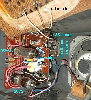
Packaged it up, and externally the radio looks the same as before, but it really pulls the
stations in. And we still have AA5 tube sound.
 I thought the heat from the tubes might cause the local osc LC circuit
to drift (the square
can with the red slug is the osc coil L, not that far from the 35W4),
but this radio seems quite stable
(no drift as it warms up, or when turning it on after many hours off it
still brings in the station I had tuned in when the radio
was warm when I turned it off).
Note that the tuning cap and the loop antenna is now a low impedance
path to the powerline, thru
a 1.25V regulator circuit inside the chip. So be sure you can't touch it
when the radio fully
assembled, else you could take a shock and probably fry the chip.
I since removed the 35W4 rectifier tube, 
and changed the series dropping heater string cap.
A silicon diode is now the rectifier. Less heat inside the radio now. I also added
a powerline RFI filter to reduce interference riding into the radio off the line.
