| An AA6 now housed in an RCA 8X541 cabinet |
.
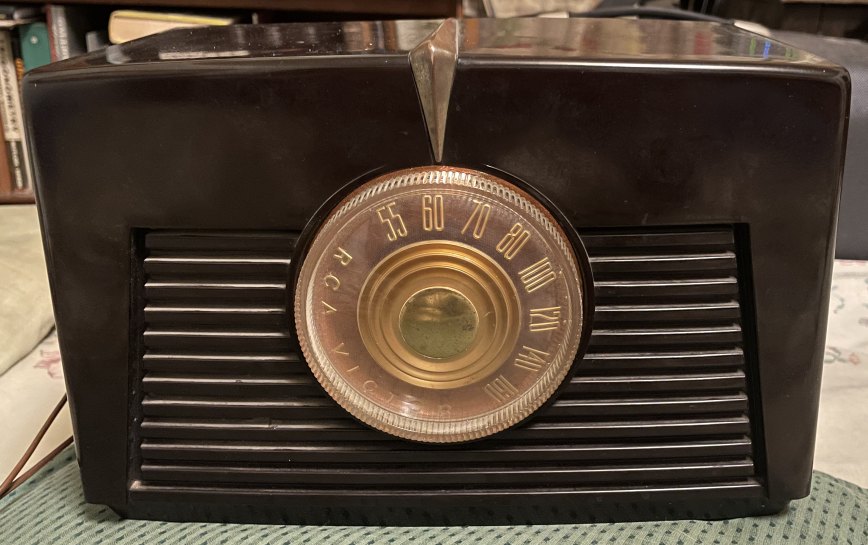
This is a 6 tube AM radio circuit board (double sided circuit board like what Motorola used in the day "PLA-cir") I installed in an RCA 8X541 cabinet, as I felt this board performed quite well and deserved a home. There's "RETIMA A 18817474" stamped on this board. "188" is the code for GE, but I can't find this board in the Beitman's I have.
This web page does read a little like a blog (written in roughly chronological order), as I had to track down some trouble I caused:
Be careful with this "PLA-cir" board, I removed and replaced the
RF stage transformer, and had about 6 hours of agony getting the radio to behave, and it's still
a little squirrley upon power up. I suspected that this old PITA board has many hairline cracks
along the traces and in the plated thru holes. I may have fixed a few of thise issues, but... No, it was the RF transformer I damaged, namely damaged
the internal cap on the primary side of it. But before I tracked the issues down to that, I soldered
bare wire to the traces and into
the plated thru holes, helped some. And added a 14 guage wire peg under the RF transformer to help
support this board (touches the bottom of the radio cabinet), to keep if from sagging. Helps some more.
Replaced the 12BA7 socket, as some of the wiring under it
was sometimes shorting to other traces. That was needed. New one is a little higher off the board to give more
breathing space for wires under it. And it seems the 12BA7 doesn't need the shield. Oh, yes it does, I hear
hum at very low volume control settiing without it. Strange... Anyway I am pretty sure I found the trouble: seems the
RF transformer has an internal 100pF cap mounted in its base (like a k-tran IF transformer) across the primary.
I'd think that this would form another LC circuit, in addition to the tuned LC circuits in the RF amp stage.
Seems I made the cap connection flakey when I first removed the RF transformer, and was trying to chase down
intermittants for the past 2 weeks (replacing resistors and caps and tubes, no dice). I'm leaving those
replacements in place, I don't want to abuse this board any more than I have to.
I removed the RF transformer again very
carefully and disconnected one end of the primary. And found about 100pF cap with an LCR meter. Tried to
use a soldering iron on the plastic piece that sandwitches the cap to bent portions of leads to try to make
a better connection, seems I broke that connection.
 Replaced the RF transformer shield can ->
To make sure it never reconnects
I first tried isolated the B+ from its connection to the transformer lug, and the primary coil (thus isolating the
internal cap in the transformer base). Used a piece of circuit board edge card connector
(double sided, no internal connection) to
create a more stable solder connections (one side to the old lug, the other side to connect the coil and B+ wire).
Connected the primary coil's B+
to the B+ on the board directly. Ugly, as I had to cut away some of the shield can to make it
fit over this mod. As the B+ wire is an RF ground, it helps replace the now missing metal shielding.
Penalty I get for removing this RF transformer without a good reason...
Decided that that edge card thing was too much of a kludge, so I pulled the transformer out and just remove the
embedded cap from the base. To do it right. Has to drill out the brass coil holder, used a hand drill so I could stop
if something goes wrong, like the coil getting spun around ripping fine wire connections. Yes, that did happen,
but only two connections got broke, and I was able to repair that. Had I used a drill press, it
would have been a disaster. Once the brass piece was removed I was able to get the sandwitch apart and
remove the embedded cap, a mica wafer. Put it back together, using the brass coil holder. I was able
to solder a ring of wire to the brass piece, at the transformer's bottom, as a substitute
for the swaged brass the manufacturer
had. I also changed the shield can. I put the transformer back on the board, soldered it and the damm thing works.
I used a new external 100pF cap, soldered beneath the radio circuit board. Radio was unstable without it. So far
it seems to be staying fixed... A few days now and it's still behaving itself. Been a few months now,
I think I can declare victory...
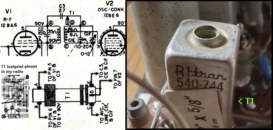
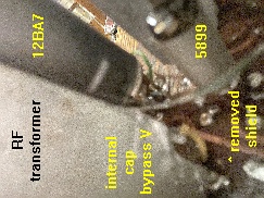
The above is what the RF transformer looks like inside its metal shield can. This from a GE radio.
And the circuit is
pretty much the same as in my AA6 radio discussed in this web page. The T1 pinout looks like one in a Silvertone radio.
Turns out using a sharp cutoff pentode 5840 for the IF stage makes for less distortion on strong stations than using a remote cutoff pentode 5899. As the signal is much bigger in the IF amp than at the RF amp. A remote cutoff curve on a large AM signal can produce distortion of the detected audio, not significant on a weak signal.
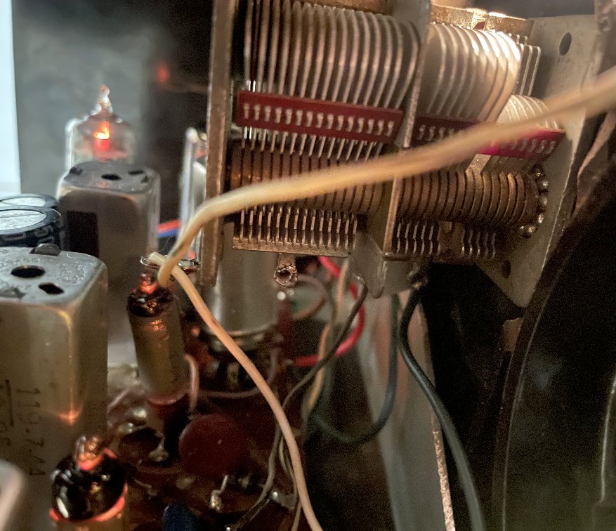
I got off ebay this cabinet (its chassis was quite rusty). I removed off this board the original tuning cap and substituted another 3 gang tuning cap (the original would twist backwards and make the tuning knob not match the received frequencies). After getting the radio circuit work with the new tuning cap (the caps were slightly different values), I mounted it to be in position for the cabinet's tuning knob position. I did have to dress the wires to this tuning cap to avoid instabilitues from undesired stray coupling.
I made a longer ferrite rod using two shorter rods. Adjusted the antenna windings (number of turns, bunching and
position on the rod) to make it resonate at the lower end of the
AM band. Use the tuning cap trimmer for the upper end of the AM band. And to keep it from falling apart I used some heat shrink over the rod and windings at the splice point. With some hot
melt glue inside the heat shrink it keeps it reasonably together and rigid.
I created a new metal chassis to mount the tuning cap and the volume control. I used a piece of paper to create a guide to make
this chassis. I placed this psper inside the empty cabinet, and marked and cut and folded this piece of
paper to create a guide to cut and bend the metal. I'm no metal smith, but I did get it to fit, using the
cabinet's existing mounting screw holes.
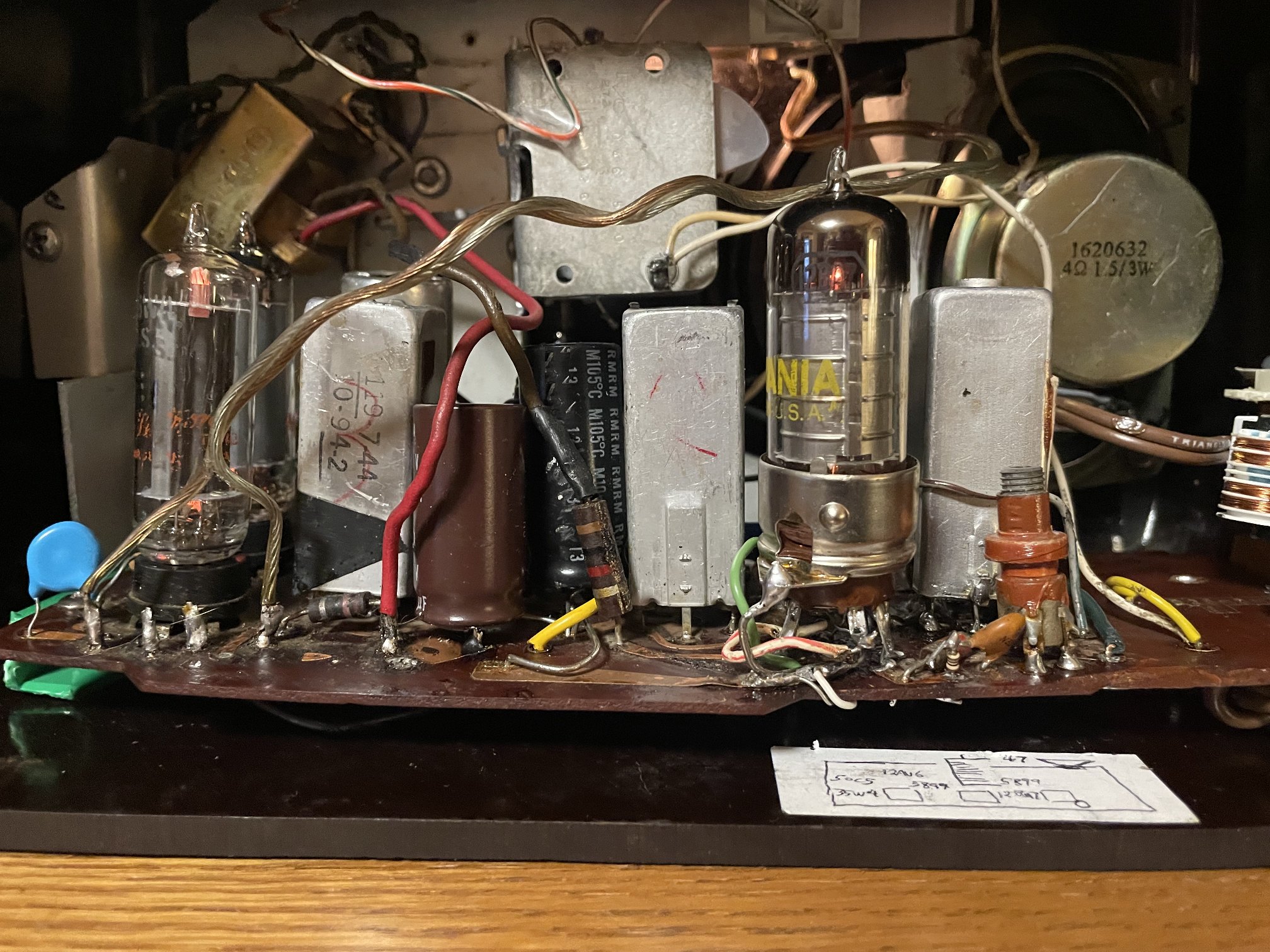
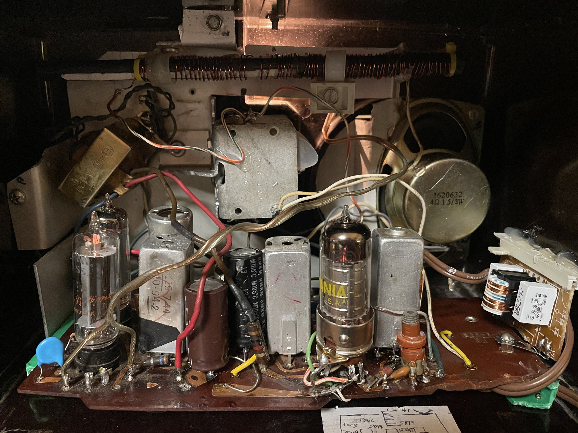
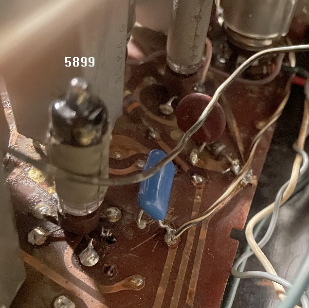
Here below is a roach's eye view of the tuning cap and the circuit board. Note the submini tubes, a 5899
(semiremote cutoff pentode) for the RF stage, and a 5840 (sharp cutoff pentode) for the IF.
No real advantage over the 12BA6's that were there, (similar transconductance)
but it was fun to do.
This does let me use a 50C5 instead of a 35C5 for a little more audio output, as the submimi tubes each are
6.3V at 150ma. 12.6V total insteal of the original 25.2V total for both the RF and IF stage tubes,
which were 12BA6's. . Note
the shielding I wrapped around the submini tubes, thin copper sheet.
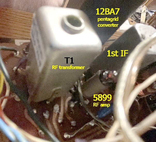
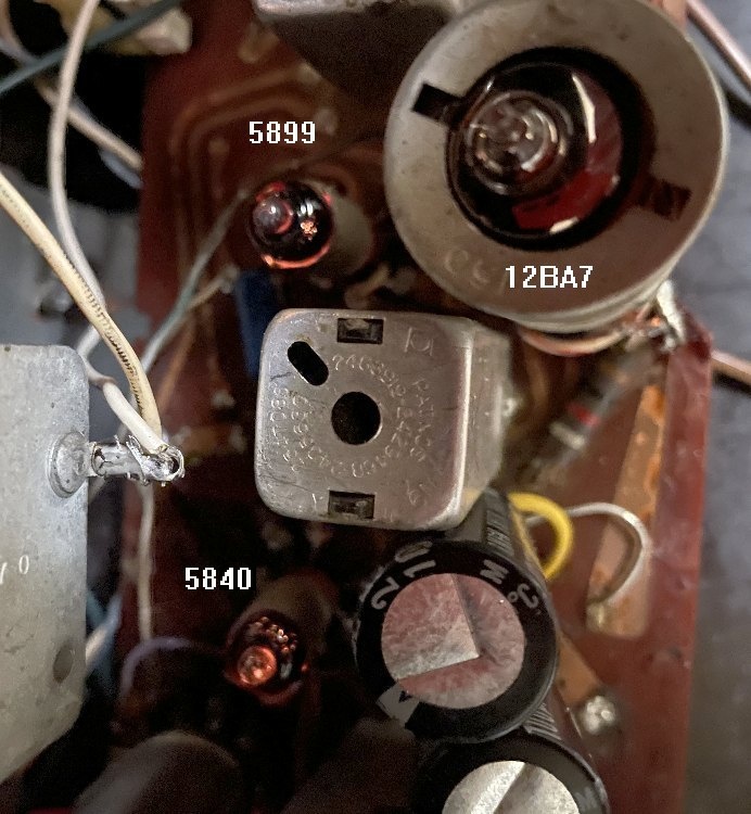
Another view of the RF amp, converter and IF amp. The 12BA7 is a pentagrid converter tube which has twice the conversion gain of a 12BE6. The AGC voltage is created by a separate diode circuit from the audio detector. I used a 1.5 meg resistor vs a half megohm, this produced a higher AGC voltage of 3.5VDC vs 3V on a local 50 thousand watt flamethrower 6 miles south of me. Which made a difference of lower audio distortion on reception of said flamethrower.
This radio, with its RF stage, heard 5000 watt WFBL Syracuse here in northeast New Jersey, about 15 miles north of New York City. (I'm an alumnus of Syracuse University, class of 1978.)
Another issue cropped up. one that was hard to pin down. Seems a high frequency parasitic oscillation was happening when the volume control nearly or all the way down. Manafests as a low amount of hum, but the presense or absense depended on the tuning of the radio front end. Possibly depending on the AVC level, depending on the amount of signal being tuned in? The chassis is connected to the AVC line, via the tuning cap's mounting.
One thing that solved it well: using a "grid stopper" of 3K right in the feed to the 50C5's control grid. Less fiddly
than other things I tried. Grid
stoppers are sometimes used in hifi audio amps to tame ultrasonic oscillations that can cause phantom hum and other
squirrelly effects. Place the resistor's body of this grid
stopper right at the tube's control grid's socket pin. This creates a low pass filter (with the 50C5 tube's
internal capacitence)
to supress the ultrasonic oscillation. Doing this also made for less power supply hum. This trick was used often in hifi
tube amps (though grid stoppers in them were more usually 1K5), but it also works in AA5s or here an AA6. I used 3K as I wanted to be
sure the parasitic oscillation would be gone, and as an AA5 audio amp doesn't have to amplify audio higher than around 8KHz, not
18KHz in a hifi amp.
Also, the above flamethrower cones in with less distortion.
Some AA6s have a fixed tuned circuit on the RF amp plate, this one has that. The coil measures 1.7mH, and with the 100pF cap that would yield a resonance at 386KHz. Would have thought that would mess up the tuning but looks like no... And a 2pF coupling cap to the secondary LC circuit, this LC circuit is tuned by the tuning cap.
I ran some simulations of this RF amp's output and input to the converter circuit. The results below:
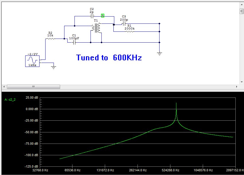
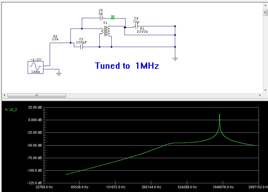
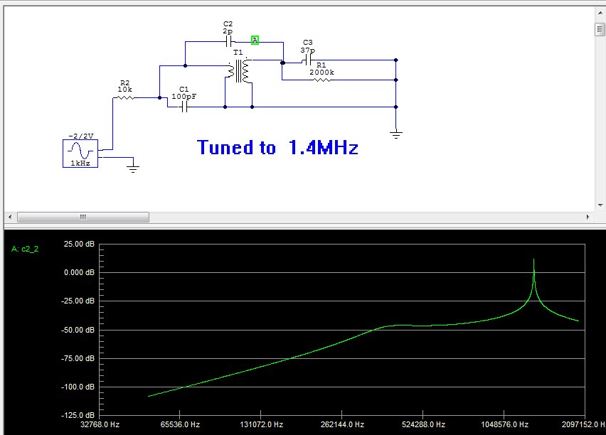
Do a "Open image in new tab" to see these better.
As you can see, the tuned LC circuit (the L is inside the transformer secondary, guessed that coupling is 70%, and C3 is the tuning cap in these diagrams) dominates. Left is tuned to 600KHz, middle is at 1MHz and right is 1.4MHz. These tuned peaks are all about the same amplitude. The bend to the left of the peak in each result is the 386KHz resonance of the transformer primary and the fixed 100pF cap.
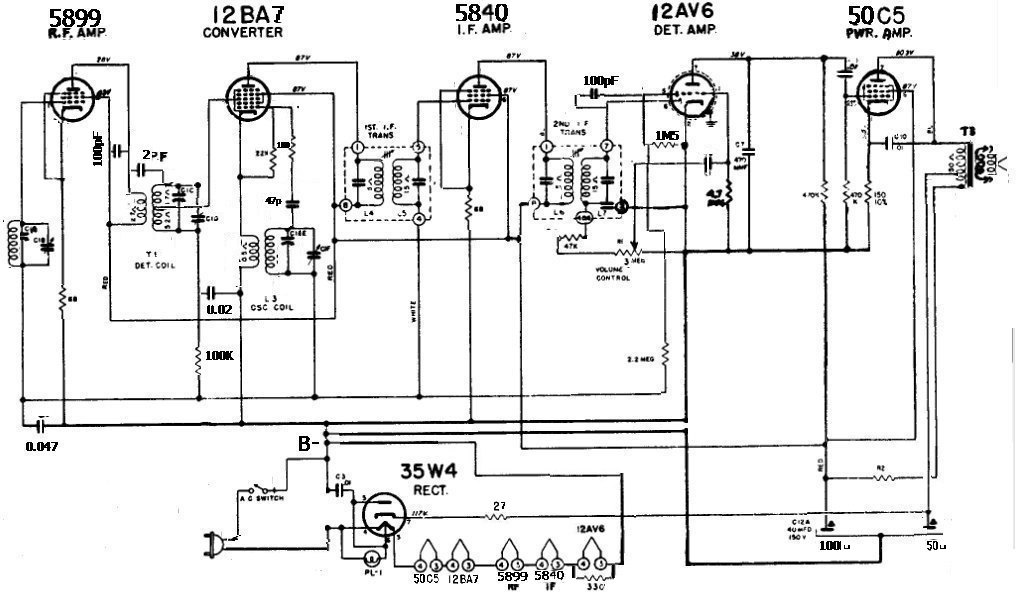
This schematic is pretty close to what "RETIMA A 18817474" did and the mods I did, note on the B- line the separate circuit paths
on the heater circuit and the filter caps. This minimizes induced hum.
Why does this AA6 has a tap on the primary of the output transformer? It's a hum bucking scheme.
The usually 1.5K resistor that usually feeds off the rectifier tube B+ is connected to the far end
of extra turns on the primary. As far as the hum ripple (interferer E) is concerned, the cap that
filters the line that feeds the output tube screen and rest of the set looks like a short to ground.
So the hum ripple sees 1.5K to ground, and the 50C5 or 50L6 output tube's plate resistance looks like
14K to ground on the output transformer's plate lead. The position of the tap is selected such that the
amp-turns of one side balance the other side. Thus the hum ripple cancels out so the speaker doesn't
hear it. The audio doesn't get signicantly loaded, as section N2 has an impedamce of roughly 25 ohms,
and the 1.5K resistor is way higher than that. J Stewart made a nice diagram which I pirated:
