Radios A thru E
This is an Admiral AA6 tube 6T01-6A1 chassis in a wooden cabinet meant for an Admiral AA5 tube radio
6T04-5B1. The 6A1 chassis uses a variable inductor to tube the output of the RF stage, and a variable 2 gang capcator for the
antenna circuit and the local oscillator.


Replaced the wax caps and the filter electrolytics in the 6A1 chassis before even powering it up. And
found that a 12SH7 sharp cutoff tube works better than the 12SJ7 it calls for. Needed to retune the
antenna cap trimmer a little. Just above is a closeup of how the variable inductor that tunes the output
of the RF amplifier was done. A spring loaded arm rests against a cam attached to the tuning dial drum
that also tunes the variable cap. The shape of this cam was designed to control the arm, which in turn
moves the ferrite bar in and out of the coil. This shape was made to have the tuning of this coil track
what the variable cap for the antenna circuit is tuning. It's possible, back in the day, Admiral couldn't
obtain 3 gang tuning caps but still wanted to make a radio with an RF stage. And someone designed
this workaround. Which actually works quite well.
Here I replaced the RF stage that was a 12SH7 with a 5899 submini tube, a semi-remote cutoff pentode.
I stuck an 8 pin submini tube socket into the center hole of the octal socket, and wired the
corresponding pin functions to the octal terminals below deck. The octal socket became a terminal strip.
Works well. I added a shield around the tube, connected
to one of the tube's cathode pins. And a center shield in the submini socket was also connected to ground,
for more shielding the input from the output. I also did this with the IF stage. That stage ended up with
too much gain, so I lowered it with a 100K resistor in parallel with the output LC of the 2nd IF
transformer (plate to B+). These tubes each need only 6.3V in the heater string (current
is 150ma) so I changed the 35L6 to a 50L6 (the two 6.3V submini tube heaters look like a single 12V, and
thus the heater string looks like a typical AA5).


Right: an Admiral AA4 
Australia:  The AWA is quite similar to an AA5, except for the use of a power transformer. Internal loopstick antenna.
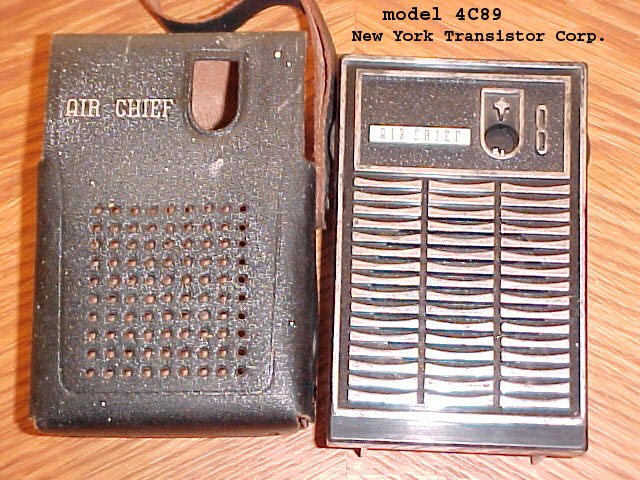
A transistor radio: 
 No, it's solid state:


.

Apex AD3201.
This DVD player has a hidden menu.
To access:
Eject the tray, then press the numbers 8, 4, 2, then 1
on the remote. Dashes should appear on the screen for
the first 3 numbers, then the hidden menu should then appear
upon pressing the last number. Use the ^ and v keys on the
remote to select "region" or "macrovision". Use "enter"
to step thru which region you want (9 is "all" or "bypass") and if you want macrovision
or not. Macrovision may make some vintage TVs or VCR channel modulators unhappy.
To save the settings, close the disc tray. You can use the "Y" video output
to feed a B&W TV set, as it will not have the color subcarrier on it.

 Airline 83BR-502. No logo anywhere on this radio.
Superheterodyne without an IF stage, 300ma heater string with ballast.
Airline 83BR-502. No logo anywhere on this radio.
Superheterodyne without an IF stage, 300ma heater string with ballast.
The Belmont transistor on the left is a typical superheterodyne set.

This Airline 62-508 radio is a superheterodyne with 150ma heater string tubes.


My brother and I had an Admiral B&W TV set just like this one
(model 24R12) back
in the '60's when we were kids. Diagram
 An Admiral FM only radio


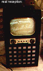
Not related to Firestone.
 This radio has my name on it!
  model: 010
Not collectable yet! with 8 track 


An Australian MW radio set, circa late 1960's: Calstan
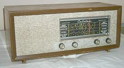
Closeup of the above dial with Australian radio station callsigns:

A tube AM/FM stereo tuner someone glued a "Sony" logo over the
"Claricon" logo.


The AM section is just like that of an AA5, but the FM is pertty good.
I made the FM a little more sensitive by changing the last two FM IF tubes from
6AU6's to 6DE6's (twice the transconductance). Also did that to the AM
IF (6BA6 to 6DE6). This was done after I did a first realignment, so I
did really see improvement after a 2nd realignment.

 A car radio (on the right) using 12V B+
space charge tubes.
A car radio (on the right) using 12V B+
space charge tubes.
 Another, tag said it's for a 1960 Oldsmonile
 This one is all transistorized. Note the conelrad
D
markings.
This one is all transistorized. Note the conelrad
D
markings.
DeWald model A500
 And a model C-800 AM-FM


My first stereo receiver, bought in 1972. If you have one of these or similar, and it
doesn't work that well, you may need to replace the electroytic caps.
I had to replace nearly all of them to get mine to
work again. While I was in it, I replaced all of them. One or two were leaking the secret sauce
onto the board.


Standard hifi web site shot to make it look impressive, though I'm sure noone is
fooled. As it's actually quite modest inside.
I think it makes only a couple watts of output power. But that's okay, as I don't blast my music.


I decided that I could use the speaker leads as a simple dipole antenna for FM. As stereo speakers
are located several feet apart horizontally, and the speaker wires that feed them will look like a VHF dipole antenna.
. I added a pair of bifilar wound
coils to act as RF transformer at 100MHz between the audio output amp and the speaker jacks. I used twisted pairs from
an ethernet cable (the insulation is good for RF work). And put both coils
end to end, to act as a simgle RF transformer. Half the winding wires are at audio ground, and I connect the ends of
those wires (at the jacks, where there will be received RF energy from FM radio stations) to the FM antenna
input of the tuner section of this receiver. The other half are the wires that carry the audio output signals to drive the speakers.
These I bifilar wound to avoid shorting out the RF. Two 0.001uF caps on the audio outputs to ground bypass any remainding RF to ground.
That RF energy gets added along with the above mentioned RF energy to the antenna. Used a terminal strip, to hold the cap connections still.
I used some aluminum foil on a section of the steel chassis next to the coil to
keep the steel from absorbing the RF energy from this antenna coil. Same reason why aluminum
was used for the housing around IF transformers in tube radios (ones in solid state sets use copper).
This set still seemed a bit deaf on FM. Swapped out the FM RF amp transistor for one that used to run in an amp at 2.4GHz.
Should work just fine at 0.1GHz, aka 100MHz. In its old circuit, the base was the RF input, emitter RF ground and collector RF output.
These stay the same in its new home.
The below tester showed that the old transistor had an hFE around 78, and the
new one about 125. Gave me some more sensitivity. As the pinout pattern of the little white pill is much different than
a TO92 transistor I still was able to get the base and collector leads thru the circuit board holes and used a short piece of wire to
connect the emitter leads to the emitter thru hole.
The emitter lead trace is a little long, but the board layout has it that way. An Infineon app note
"6 GHz band LNA application circuits, figure 2" suggests that this trace may be functioning as an inductive emitter
degeneration microstrip line. I tried bypassing the emitter closer to this transistor, but it went unstable,
disabling FM reception. So it seems this transistor wants this degeneration. The old transistor may have wanted this
too. Below is the package outline. To select the best emitter resistor, I did it a crude way. Used a 1K trimpot as the emitter resistor and
while listening to a weak FM station, adjusted this trimpot to get best reception. Checked other stations for
good reception. After finding a good trimpot setting, removed it, measured it and used a similar value fixed resistor. 300 ohms.

Additionally I decided to try changing the transistors in the FM IF strip.
I desoldered one transistor from the IF strip. and using one of these testers (pictured below) determined the pattern of the
base, collector and emitter pins, and the hFE gain. Which seemed a bit low. Normally most circuits are designed to not
much care about hFE, but in an IF amp stage the enitter is RF bypassed to ground, so the gain at RF frequencies will
be more dependent on hFE. I used Augat style machined IC sockets I cut up to accept leaded transistors, so I could try other transistors
from my junk box that tested with higher Hfe. Makes swapping candidates easier, without destroying the rather fragine Japanese
circuit board. Good thing I did, as some transistors I tried didn't work too well to not at all at 10.7MHz. But did find
ones that did work at higher gain than the original transistor did. Tempted by success, I did 2 more IF stages.
The FM gain is a little higher, and I checked the AM gain.
As two of the three transistors I swapped are used in both AM and FM, I wanted to be sure the AM wasn't messed up.
Found that AM has higher gain on weak AM stations without distorting the
local flamethrowers.


Had to replace a noisy transistor in the audio amp board, right channel. First transistor the
audio signal from the volume control hits. Found the noisy transistor using freeze spray.
And found a reasonably similar geranium transistor having a similar hFE and B-E drop. Used Augat socket pins
(as the board is fragile) so I could easily change this replacement transistor in case the circuit doesn't like it.
but the circuit is happy. Close enough gain as the other channel. Oh, the replacement is in a TO-5 case
instead of the usual Japanese barrel TC-1, TB-1 or TO-1, but it works well.
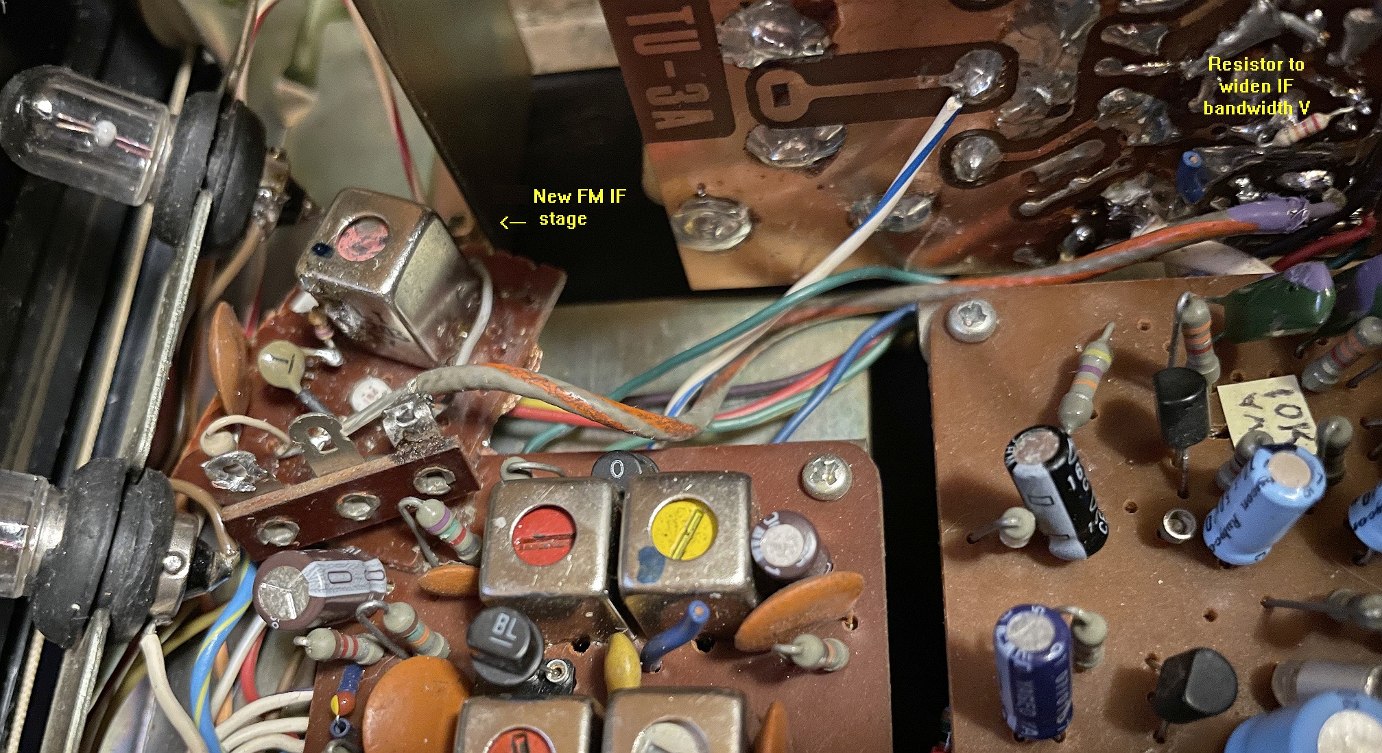
Added an additional FM IF stage (the one with the pink adjustment screwhead), as
this set seemed a bit deaf. Inserted it between the tuner board and the AM and FM IF
and detectors board. The AM, FM mono, FM stereo and AUX switch also switches the FM IF RF and the AM IF RF signals. So the new FM
IF went in front of this switch as well. The tuner board has an FM IF transformer (10.7MHz) and its secondary has bias to
feed the first IF transistor on the IF board. I intercepted that to have this feed the new IF stage's transistor, and I also
fed this bias to the new IF transformer's secondary to feed the old first IF transistor of the IF board.
I had some trouble with 10.7MHz signal leakage causing feedback oscillation so I changed from twisted pair wire to small coax.
The coax shield is an RF ground but carries the above bias to the new IF transformer's secondary.
FM stereo reception sounded noisy and distorted on many stations, so I figured that the IF was too narrowbanded. Aded some 22K
resistors across the IF transformer primaries (which are the LC circuits), except one where I couldn't get at the
entire primary winding, so I used a 4K7 resistor from one end to its centertap (same effect, as roughly half the winding
would need a quarter the impedance; a quarter of 22K is very roughly 4K7, but close enough). Seemed to help without too much sensitivity penalty.
Less noise and distortion on stereo reception. You need about three times more bandwidth for stereo signals than mono signals.
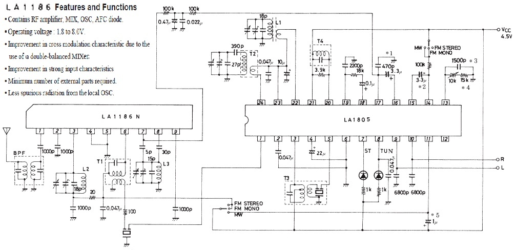
I acquired another Decca, and I also acquired an AM/FM stereo board (from a Sharp AM/FM stereo cassette recorder)
built around the LA1186 FM front end and LA1805 AM front end and AM/FM IFs and FM stereo demodulator chips.
The FM front end uses a duble balanced mixer. Double balanced mixers are able to provide very high levels of
performance in RF or frequency mixing applications. The action of the double balanced mixer means that the
input RF and local oscillator signals are balanced out and their level is considerably reduced at the output
by having differential circuits on their inputs. A doubly balanced mixer structure provides lower
LO signal at the output IF port This reduces the need to remove the often unwanted RF and local
oscillator signals at the output and reduces the effect of these input signals causing intermodulation distortion.
Typically, a large LO signal at the IF output port leads to poor mixer intermodulation performance and can also cause
compression in the first IF amplifier.
The advantages of a double-balanced mixer over a single balanced mixer are increased linearity, improved suppression
of spurious products (all even order products of the LO and/or the RF are suppressed) ant
the inherent isolation between all ports. An advantage is increased linearity: Double Balanced
Mixers offer better intermodulation performance and a
higher 1dB compression point compared to simpler unbalanced designs.
I removed the old tuner, IF and stereo demod boards and installed the LA1186 and LA1805 board. I kept the old audio amp board.
As it includes the tone control circuits. It receives FM stereo signals better and also AM stations. I did keep the old tuning cap,
as I needed it to serve as in intermediate mechanical pully to then pass mechanical tuning pully strings to the new board. The
new board was too wide to sit at the old tuning cap's mechanical location.
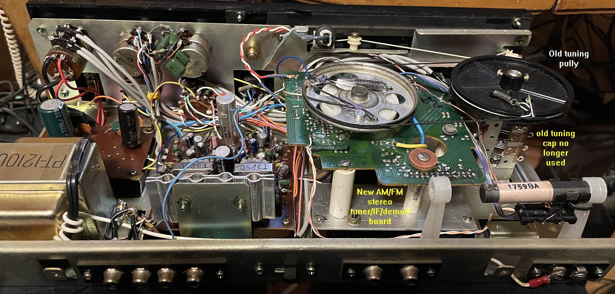
In place of the old IF and stereo detector boards I used a piece of sheet metal to mount ceramic supports on. Which in turn
supports the new board. And you can see how I ganged the new tuning pully to the old pully. It takes more effort to twist the set's tuning knob,
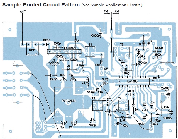
though... Below is a board layout from the app notes of the LA1805 datasheet, which is very close to wnat Sharp did
on the board I used here. Oh, and of course I got the left and right channels backwards, so I had to go back
inside with the soldering iron to swap them correct.
I did not use3 Chat-GLP to write this. 
 this one in 1996
Vacuum tube stereo amp 
Less hum in the phono preamp if the 12AX7s are replaced
with 7025s.

This should be in the E section, but there's some leakage in this web site
