
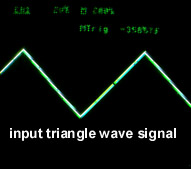
 input signal
The range distance of this microtransmitter is only a meter or two, so the target radio set will need to be nearby. You really don't want this signal to travel very far, or else you could cause interference with radio station reception at a neighbor's home. Also if you hold an FCC license, you don't want to transmit significant power "out of band".
input signal
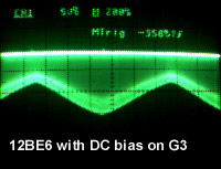
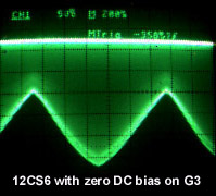
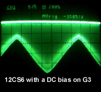
This diagram specifies the use of a pentagrid tube with a sharp cutoff characteristic, such as the xCS6. It says that a 6BE6 will distort the audio without feedback. The rest of this paragraph and the first four oscilloscope pictures below show performance without the feedback loop installed. If one backs off on the modulation depth, reasonable linearity can be achieved with a xBE6. This modulation depth dictates the amount of volume the AM radio will "hear". Applying a little bit of DC bias on the G3 grid of the pentagrid tube (xBE6 or xCS6) can improve the linearity some. This can be done either by biasing the G3 resistor with a source of DC, or using a cathode resistor from ground to the oscillator coil cathode winding (bypass this resistor to ground). The xBE6 in the oscilloscope views below didn't need or want much DC bias. The ratio of max to min modulation depth is around 2 to 1. This is much less than commercial radio stations, they run something like 10 to 1. The xCS6 can produce more modulation, but requires more DC bias. Notice the distortion with zero bias. If I back off on modulation depth I can reduce this distortion, but a better solution is to apply the DC bias. Its ratio can go up to 3.7 to 1 before distortion sets in objectionally with an optimal amount of DC bias applied. I used a 1K trimpot to adjust the bias.
A 5915 tube looks to have similar sharp cutoff curves on its G3 like the 6CS6 and should work as well. So should a 6BY6 as its G1 and G3 have sharp cutoff characteristics.
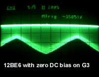
 Views on plate of
the pentagrid tube. Audio is an 800Hz triangle wave.
Views on plate of
the pentagrid tube. Audio is an 800Hz triangle wave.
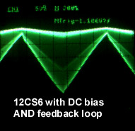
The 12CS6 does work better than the 12BE6, but you're more likely to have 12BE6's on hand than 12CS6's. The required reduction in modulation depth will make for about 4 dB less audio volume. That difference can be heard, but isn't too severe.
Add a feedback loop to reduce distortion and increase modulation level
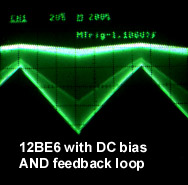
One can improve the microtransmitter by adding a negative feedback loop that samples the AM modulated carrier, detects it, and then applies it to the xAV6 input audio buffer's cathode. This causes the xAV6 to produce an inverse distorted signal from its plate to be applied to G3 of the pentagrid tube. This counters the distortion of the pentagrid tube to produce a reasonably undistorted AM modulated carrier. One now gets a max modulation ratio of 4 to 1 with a xBE6 or 8 or 9 to 1 with a xCS6 pentagrid tube.
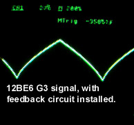 Corrective predistortion as applied to
G3 resulting from the feedback loop action as it corrects for the
12BE6's remote cutoff characteristic.
Corrective predistortion as applied to
G3 resulting from the feedback loop action as it corrects for the
12BE6's remote cutoff characteristic.

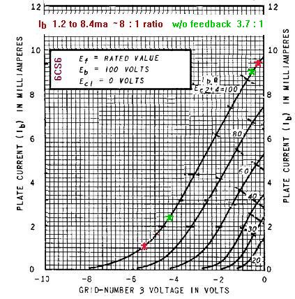
Curves from the 6BE6 and 6CS6 datasheets roughly predict these results.
These show plate current vs. grid 3 voltage with the screens
(g2 and g4) and plate at 100V.
Aside from the diodes and some resistors, all the parts needed for this microtransmitter can be found in an AA5 radio set. Except also for a 4uf 25VAC voltage dropping cap for the heaters now that the 12BA6 and 50C5 are now removed, if one then uses the 12BE6, 12AV6 and 35W4 in an AC/DC setup. If one wants to use all tubes and no silicon, a 12AL6 also works well. The bias on the 12BE6 can be changed with this change, as there are no diode drops in a vacuum tube diode. Be aware that the feedback loop gain will be affected by the loading of the pentagrid tube plate by the antenna. You could use a xAU6 sharp cutoff pentode as a buffer amp. Use a 1K cathode resistor and a 10K resistor in the plate circuit. Use a 10K resistor to ground for the grid, and a 3300pF coupling cap from this grid to the pentagrid plate. The screen grid goes to B+, and suppressor grid to ground.
Be sure to use a polarized power plug so the system ground is connected to the powerline neutral. But be sure you use a 0.1uf 250VAC capacitor to isolate the system ground from the external audio source ground with respect to 60Hz and DC just in case the power outlet you use is miswired.
Or use a power transformer for isolation from the line. In
which case you can use tubes like the 5915 or 6BY6 and not worry
about heater supplies off the line. And avoid shock hazard and
ground loop issues.
I used a pair of transformers from radio shack, one a 25.2V CT
at 450ma and another 12.6V 300ma fed backwards to produce local
B+ via rectifiers and filter cap. The heaters connected to half
the 25.2V secondary, and the other transformer connected to the
other half. 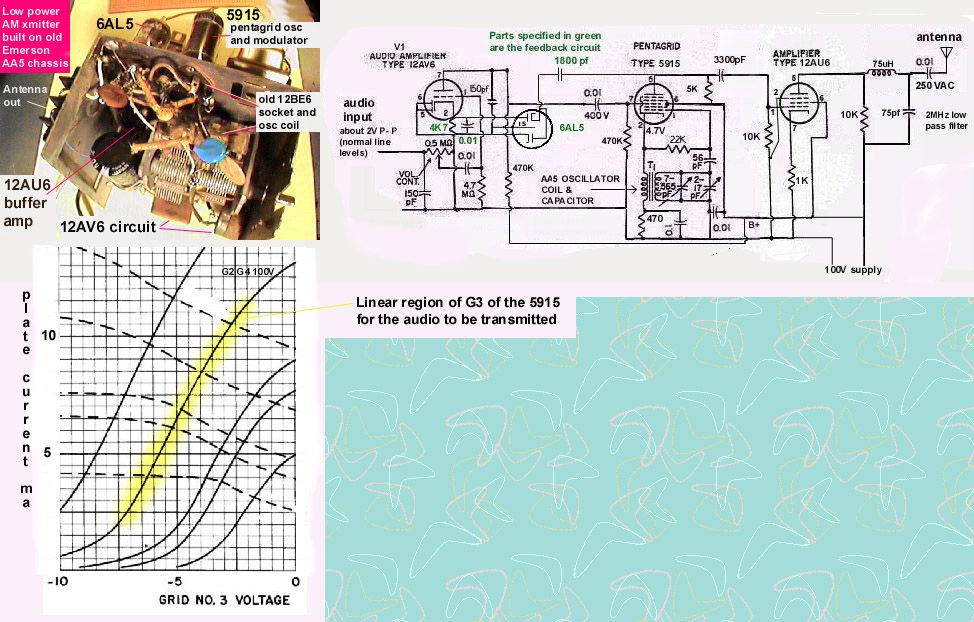 The above described 12AU6 buffer amp is hidden from view here
on this chassis.
The above described 12AU6 buffer amp is hidden from view here
on this chassis.
One could put the 50C5 to good use as an RF amplifier to boost the signal strength about 10dB. The 12BE6 plate now feeds not the antenna now, but thru a 1000pf cap to the control grid of the 50C5. The grid resistor is chosen to create an RC circuit that will pass the RF but stop the residual baseband audio present on the 12BE6 plate. The 50C5 plate has a 1K resistor which develops the output RF voltage. A small 0.01 250VAC cap couples this RF to the wire antenna. See diagram below. Realize that the output signal is full of harmonics, so this transmitter is not too clean. The output is around 20 to 30mW, which is low enough power to be legal per FCC rules part 15 (100mw input to the final amp, 50mw effective radiated power). Crudely put, if you can measure with a scope an RF signal of 28V peak to peak across the 1K resistor, that would be 10V RMS signal with a source impedance of 1K, which gets you 100mw. Max transfer of power happens if the load looks like another 1K impedance. Now the signal will look like 5V RMS across 500 ohms, which is a total of 50mw. But only half that is delivered to the load 1K, so you radiate 25mw. Odds are that the antenna will be a poor match, so actual radiated power will be lower. The FCC also restricts range to approx 200 feet or less. So if you can't hear it on the car radio (be sure to extend the whip car radio antenna all the way out) 200 feet away, you should be safe. If you do hear it that far, just decrease the 1K resistor to a lower value.

If you want to avoid running wire all over the place, you could connect the antenna output line to a conductive water pipe, heating duct, the shield of the CATV cable outlet, or radiator pipe. These should be connected to ground somewhere near the safety ground that is used for the electric utility feed at the main breaker. The powerline neutral should be grounded at this and only this point as well. This combined with the microtransmitter's ground connected to the powerline neutral (we hope!) will create a large loop with the itemized conductor above that is connected to the antenna. This should create an RF field that will fill most of the house. Check to make sure you don't exceed a range of 200 feet.
If you connect this transmitter to a computer's audio output, you may pick up a lot of hum. What is causing this hum is the small 1 to 2 volts dynamic voltage difference between the powerline neutral and the safety ground. Current thru the neutral will cause a small voltage to develop because of the small amount of resistance in the house wiring. This resistance is normally about a quarter ohm. To eliminate this hum you could connect the transmitter ground line to the safety ground instead of the powerline neutral. Problem with this is that you're not supposed to routinely return current thru the safety ground. If the safety ground ever goes open, the computer equipment ground will become "hot" with powerline voltage. The transmitter won't operate like this though. Another not so great solution is to tie the neutral and ground together, assuming that the neutral is in fact not "hot". Sparks if it is hot!

If you still have an old CRT VGA computer monitor in the closet or basement. you could use the
video amplifier CRT driver circuit as an RF amplifier. As VGA video ranges from near DC to around 30MHz,
and the peal to peak amplitude of the video applied to the CRT cathodes is something like 20V (impedance is around 3K
which should be okay for a short long wire antenna), it
would make a passable RF amp. Passable in that the linearity of these chips, adequate for video work,
would need harmonic filtering if you were to use it as a QRP ham transmitter. But it works well
enough as an AM modulator for use inside your home. Detected AM audio from a radio sounds great.
The above diagram shows a LM2405, but it's likely your monitor uses some other chip. Keep the chip on the circuit board, as it will include RF bypassing and such to keep it stable at RF. You'll need to remove other chips that do video signal clamping and or OSD insertion, as you don't need or want clamping on an AM modulated RF signal. You can strap together two or three channels together, but you should sum the outputs together downstream of the output resistor (the 100Ω) and capacitor (the 0.1µF). This keeps the outputs from frying if one is slower than another, as they see about 150Ω or more between them. And keeping DC bias drifts from being a problem as the 0.1µF caps will block the DC from each of the chip's outputs. You should have much experience in tube and solid state circuits, as this isn't a task for a beginner, though. To find a datasheet on your particular chip, try https://www.digchip.com/ first.