AAR-32 frequency display modified to
indicate with a small "1" when the
extended band mode is selected. The
numbers are multiplexed similar to
methods done in calculators.
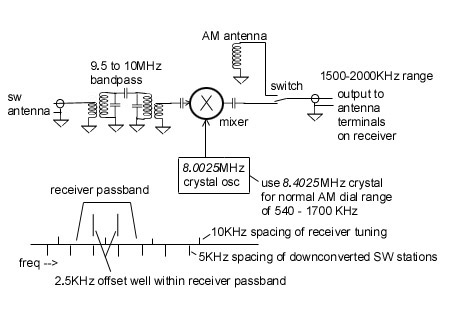
My Akai AAR-32 stereo set was designed and programmed to tune the regular FM broadcast band, and the old AM MW band from 530 KHz to 1610KHz. But now there are stations above 1610 KHz. In the extended AM band up to 1700 KHz. In an analog tuned radio, getting the extended band is just a matter of re-tweaking the local oscillator and antenna LC circuits capacitor trimmers (usually found attached to the tuning cap frame). Just reduce the capacitance of the osc trimmer while listening for extended band stations. Then trim the antenna circuit for sensitivity.
But in a microcontroller controlled digital tuned receiver, this won't be so simple. In my Akai receiver, the microcontroller scans the user front panel pushbutton keys, then sends a sequence of digital values to the Phase Lock Loop (PLL) chip. The Akai uses a TC9125BP PLL chip. This chip has its data and address lines multiplexed together. This data tells the chip by what value to set a divider circuit fed by a reference oscillator. This results in a pulse train that is compared to the analog voltage controlled local oscillator, and adjustments are made automatically to that local oscillator to get it on the desired frequency, namely (station frequency + IF frequency). For more on PLLs, do a web search on phase lock loops, or even go to an old fashioned paper book engineering library.
The TC9125BP chip uses binary coded decimal to load the divider
registers. As the data/address bus is 4 bits, nibbles are
sent and strobed into the chip's registers. Data are numbers
(in binary) from 0 to 9. Address make use of invalid binary
encoded decimal codes (from 11 to 15). An address is sent first,
strobed by the load line, and the next nibble is the data to
be loaded into the register (upon the next load strobe).
Four pairs of addresses and data are sent, as the decimal representation
of the divide value is 4 digits long. See the timing diagram.
Note that the spoofing leaks into the next address nibble, but
this leakage is ended before the next strobe comes along. So there is no
misprogramming done.
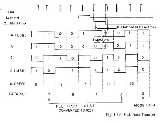
For the AM band, the value to be loaded is equal to the frequency
of the desired radio station plus the IF frequency (in this set, 460KHz).
For a station on 660 KHz, it would be (660 + 460)/10 = 112.
So the value "0112" would be sent. If we wanted 1660, we would
need the value "0212". But the microcontroller was programmed not
to ever send this value, as it would make the radio tune outside
the old AM band. However, we can make a circuit that detects
when the "hundreds" digit data is to be sent, and change say a
digit 1 into a 2. With this circuit enabled, punch up "660"
on the "dial" and the "hundreds" digit modified by our circuit,
the PLL chip sees the value "0212" instead of "0112". And cause
the receiver to actually receive a station at 1660 KHz instead
of 660 KHz. This spoofing doesn't stop at 1700 KHz, my receiver
could accurately tune up to 2030 KHz (though there are no AM stations
up there). This is limited to the range of the controlled analog
oscillator. Connecting an indicator to pin 13 (frequency lock
in) of the PLL chip will tell if
the PLL is locking or not.
See diagram for spoofing circuit block diagram.

As mentioned above, I was able to
tune as high as 2030 KHz and maintain lock. This includes
the ham radio 180 meter AM and single sideband (SSB) phone (voice)
communications band. I was able to listen to Amateur SSB
communications with the Akai. Listening to SSB with an AM receiver can
be done by using a second AM radio. Tune the local oscillator
of the second AM radio (by tuning to around 1500 on that radio)
to "beat" with the SSB signal to produce
understandable audio. Leakage of the local oscillator from the second
radio into the
Akai receiver's antenna will do the trick.
This exact description is probably of limited direct application to sets that use the above PLL chip. But the overall concept to be gotten from this web page is that the digital commands from the microcontroller in your set can be intercepted and "spoofed" to cause the PLL to tune beyond the original design range. You'll need documentation of the commands your set uses, which may be provided by the service manual. Reprogramming the microcontroller is possible in theory, but would rarely be practical.