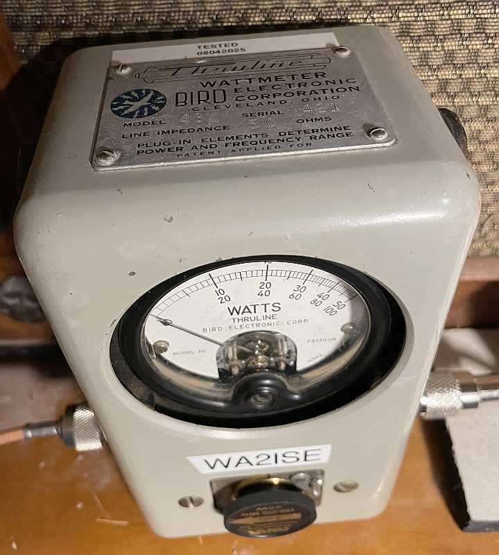
Enter any two known values and press "Calculate" to solve for the others.
For example, a 1000pF capacitor or a 25.3 μH inductor will have 159Ω
of reactance at a frequency of 1 MegaHertz. Fields should be reset to 0
before doing a new calculation.
Inductive Reactance (Xℓ) = 2πFL
Capacitive Reactance (Xc) = 1 / ( 2πFC )
Resonant Frequency (Fo) = 1 / ( 2π√LC )
Adapted from http://ourworld.compuserve.com/homepages/Bill_Bowden/XLC.htm which is no longer there.
Modifying old CB radios that used the PLL02 chip, this mod steps every 5KHz
instead of 10KHz steps
Adapted from
An Inexpensive CB to 10 Meter Conversion by Jerry Coffman, K5JC some of which I quoted here. First do the mods
as described there, before doing mine for the 5KHz steps. Once you tune all the coils and transformers as he
described, you don't need to do it again after doing my mods. You only redo the channel switch wiring.
"In acquiring radios for my experimentation, I soon discovered there were very similar
radios to the three crystal, PLL02A PLL based ones I was looking for, but these radios had
only two crystals, without a 11.0866 MHz crystal to be changed! The PLL02A was still there,
but no suitable crystal to change. So, how do you move a radio up about 2 MHz in frequency when you
do not have a crystal to change? To begin, I downloaded a copy of the service manual5 from
www.cbtricks.com for the Hygain 2702 model radio, which was a typical PLL02A PLL radio, with only
the 10.240 and 10.695 MHz crystals.
These radios use the various pins on the PLL02A to apply or remove 5 VDC to change frequency,
using the channel selector switch. By modifying connections directly to the PLL02A, the frequency
produced can be changed. Pin P0 adds/subtracts 10 KHz; P1 20 KHz; P2 40 KHz; P3 80 KHz; P4 160 KHz;
P5 320 KHz; and P6 640 KHz. P7 was hardwired to always have 0 VDC and P8 always had 5 VDC applied to it.
In studying the PLL02A specifications 6 shown in Table 2, I discovered P7 should add/subtract 1.28 MHz and
P8 should add/subtract 2.56 MHz. In these 2 crystal radios, if a pin has 5 VDC, it does not add frequency;
if has 0 VDC, it adds frequency. A little work with the voltmeter showed P7 is always 1 (0 VDC) and P8 is always 0 (5 VDC) .
Assuming I could get the VCO to work at the higher frequencies, by removing 5 VDC from pin P8, I
could raise the frequency of the radio from 26.965-27.405 MHz to 29.525-29.965 MHz.
Now, that would be a great start, just a little high in frequency!
I located P8 on underside of the circuit board and quickly cut the traces on both sides. A short jumper was soldered around pin P8.
Now, would it work, or do I now have another radio for the parts box? First step is to adjust the VCO
voltage. TP8, located near L1, and ground would have to be between 1.5-3.6 volts, on all channels.
Note: Do not use chassis ground, use the -13.6 VDC connection. And be sure to use the proper adjustment
tool, as the ferrite slugs break easily. Slowly adjust the slug in L1, while monitoring the voltage on TP8
for about 2 volts. Turning the slug clockwise, brought the voltage down to 2 volts when on channel 1!"
I found I needed to remove L1 and change the little 24pF cap inside it (it's like an IF transformer) to a 20pF cap.
Then I could adjust this coil so the ferrite slug wasn't sticking out so much. I mounted this new cap under the board, as it
would not physically fit inside the L1 can. But it still forms the needed LC circuit.
"In studying Table A in the service manual, channels 10-38 could be lowered in frequency by 640 KHz by hardwiring +5 VDC to pin P6.
Channels 1-9 already have +5 VDC on this pin. This would have channel 10 on 28.995 MHz and channel
40 on 29.325 MHz, covering the 10 meter AM band perfectly! So soldering a wire on the circuit
board from the area where pin P8 had gotten +5 VDC to the connection P6, should put the radio into
the 10 meter AM band. This little jumper was soon in place. In theory, channel 1-9 should go from 29.525-29.625 MHz, part of the 10 meter FM
band, 5 KHz off frequency, and channels 10-40 should go from 28.995-29.325 MHz, covering the 10 meter AM band. These channels and frequencies are
shown in Table 1. I checked the VCO voltage and adjusted L1 so TP8 varied from 1.5-4 VDC on all channels.
Note: if the VCO will not lock, get it working before going any further. Now for the
receiver and transmitter adjustments.
These are the steps I followed: Set the handy service monitor or signal
generator to 29.125 MHz. Set the channel selector to channel 20, and open the
squelch. Increase the signal, until it can be heard in the radio's speaker. Standard
adjustment procedures were used: decrease signal strength as the signal becomes too strong,
as adjustments are made. T1, T2, T6, and T5 were adjusted, in that order.
How did it work? Less than 1 uv sensitivity! In fact, 0.5 uv or less.
Now for the transmitter. Hook the radio up to a power meter and a dummy load. You will not have any
output power, yet. Set the radio to channel 20 and tune a receiver across the room to 29.125 MHz and
adjust the volume so you can hear it at the radio. A large S-meter on the receiver is helpful, also.
Adjustments L5, T3 and T4 are critical here, as they form a filter, to only let a narrow band of frequencies
through to the final amplifier. As you key the transmitter, you should hear the transmitted signal.
If not, either move the receiver closer, or use a better antenna. Slowly adjust L2, listening for a change
in tone on the receiver across the room and watching for the S-meter increase. Unkey the transmitter between
adjustments. If you do not notice an improvement, move the slug back to where it originally started. You may
need to use only a short wire for an antenna on the receiver, as you will overload it, if not careful. Again
key the transmitter and adjust L5 slowly, listening carefully. About 1/4 turn clockwise should be close. Then
move to T3. Slowly adjust the slug clockwise, listening for a stronger signal in the receiver, and watching the
power meter for any movement. Again about 1/4 -1/2 turn should be all that is required. No power output may be
obvious on the power meter yet, but you might already see some power output. T4 is next. Only about a 1/4 turn
is all that should be required.
As you adjust T4 clockwise, at some point, the power meter should show measurable power. If not, go back
to L5, T3, and T4 and tune slightly until you have measurable output and adjust for maximum signal output,
as measured on the power meter. These filter adjustments are quite narrow and may require readjustment.
Then repeak L2, L5, T3, and T4 for maximum power output.
Now for the PA adjustments. Adjust L7, L11 and L12 for maximum output, in that order.
They should tune counterclockwise. Power output should now be about 4 watts. Use your
frequency counter and verify that the radio is transmitting on 29.125 MHz and not elsewhere.
Check for output and frequency on channels 10-38. If power drops off on some channels, you may
want to adjust L2, L5, T3 and T4, until power output is uniform from 28.995-29.325 MHz, channels
10-40. Low output on channels 1-9 is not a real problem, since you do not want to transmit AM on the
FM portion of the band, anyway.
Let's start looking for a suitable radio and break out the solder iron. A quick search of the internet showed several radios use this board.
A Google search revealed page 91 of? "Screwdriver Experts Guide to Peaking Out and Repairing CB Radios" by Lou Franklin lists several late 2-crystal AM
CB radios using the PLL02A PLL chip. If you find a radio with a PLL02A chip, and only two crystals,
10.240 MHz and 10.695 MHz, it is probably a candidate for this conversion. The circuit board used by all these radios is essentially the
same, and suitable for conversion to 10 meters. Some radios have more options than others, but they use
the same basic circuit board, with the major components in the same locations. On some models,
L5 was not there, but the other adjustments were the same. I have converted models
Midland 77-857, Kraco KCB4020, J.C. Penney 981-6204 and several others, using the techniques I have described."
Above quoted in case the link becomes broken.
Okay, now you got it working fully, you can then pregress to my mod:
I want to get most of the 40 channels in the AM subband of 10 meters (29 to 29.2MHz), and doing mostly 5KHz steps
will do this. Oh, some frequencies will be skipped, just like before, and as when the radio was a CB set.
But all but one skip is 10KHz instead of 20KHz.
 And renumbering by repositioning the knob:

Note that the top and bottom of the
subband happens, in the left chart, between channels 9 and 10.
Undo the channel selector knob's setscrew, reposition
it to put channel 1 where channel 10 was, tighten the setscrew. Then the chart on the right becomes the valid one.
The XOR gate below will make this happen, instead of putting
channels 1 thru 9 (left chart) outside the AM subband if you didn't use the XOR gate.
First, locate C61 (electronically between Q2 and the PLL02 chip) and remove. We will wire up a flip-flop, a 74LS74,
here. Q2's emitter will feed the flip flop's clock pin, and its Q output will feed the PLL02 chip, pin 3. Wire the
flip flop's D input to the flop flop's
inverted Q output. 5V and ground as well. This will divide the 10.24MHz reference frequency in half. I used a SMD 74LS74 chip, soldering thin stiff leads
to it and mounting it in the air above where the cap was. In theory, the PLL02's FS pin should
also do this, but it didn't work for me; it gave me a divide by 1139 instead of 2048, yielding steps of 8.89KHz, not
useful. This flip flop combined with the PLL02's divide by 1024 will give me the 5KHz steps I want.
Once you do this, you'll find a new frequency on channel 13 (left chart) shifted up to 29.65MHz vs 29.035MHz we had before.
That's to be expected, as the next step is to redo the channel selector switch wiring.
Cut P7 (pin 8 of the PLL02) free from ground, and tie it high to the 5V supply. This should make channel 13 (left chart) be on
29.01MHz. Channels 11 thru 40 (left chart) should be as on the above left frequency table. Channel 29 (left chart) should now be 29.1MHz, and you may want to tweak
L1 to get the VCO voltage, TP8, to midrange, about 2.5V or so.
Now to take care of channels 1 thru 9 (left chart). Disconnect the PLL02's P6 (pin 9) from the channel selector switch.
I connected this disconnected selector switch's P6 to one input of the XOR gate (a 74LS86). You will need a 1K
resistor to ground to make sure a low is actually low (the PLL02 chip has pull down resistors inside it).
Cut the P4 trace between the channel selector switch and the PLL04 chip (pin 11). The selector switch side feeds the
other input of the same XOR gate (and use another 1K pulldown resistor), and the XOR gate's output now feeds the P4 of the PLL02 (pin 11). Connect the
gate's ground to ground, and Vcc to the 5V supply (which may start to sag a little, so find R5 and parallel a 200 ohm
resistor to it, this should bring the 5V supply back up). A better mod would be to use a pass transistor
and a 6V zener diode to create a simple regulated 5V supply. See below diagram. Remove R5 and the old zener. Channels 1 thru 9 (left chart) should now be around 29.2MHz, as per the above left table.
As 29.000MHz is the most popular frequency, I used some "glue" logic to make the new channel 2
create 29.000 instead of 28.995MHz. I used a triple input triple AND gate 74LS11 and the previously unused XOR gates
to make the logic. From the selector switch, if P0 = low, and P1 thru P5 are all 1's, then I use a pair of XOR gates to
invert P0 and P1 before feeding it to the PLL02 chip. If not, P0 and P1 are not inverted. Gettin' ugly...  As the phase comparitor inside the PLL02 is now running at 5KHz instead of 10KHz, I doubled the caps in the loop
filter (C1, C2 and C3). Didn't seem to make a difference, but did it for completeness.
As the phase comparitor inside the PLL02 is now running at 5KHz instead of 10KHz, I doubled the caps in the loop
filter (C1, C2 and C3). Didn't seem to make a difference, but did it for completeness.

Build an RFI sniffer:

To track down exactly where RFI is coming out of a computer or
other equipment, use this RFI sniffer. It's a ferrite toroid ring
with a gap cut into it. Several turns of wire connect to coax that
then feeds into a receiver or spectrum analyzer (I'm sure you have
one handy!). The gap is the sensitive area. It will pick up RFI
magnetic fields. Thus you can identify wires or other leakage areas
with RFI on them.
It takes a long time to file the gap into the toroid; your needle
files will get dull. Don't push too hard, as ferrite is fragile.
You want a narrow gap on the outside part of the ring, so file from
the inside. A gap about the thickness of a fingernail is good.
Depending on the ferrite material, this sniffer should be good for
HF and VHF.
For low frequency work, use a tape head from an audio cassette machine.
The center of the front part of the head (where the tape used to pass over)
will be the sensitive spot.
HF antenna tuner: 

A 50Ω low pass filter, cutoff at 50MHz 


Curve upper left was done with an old HP network analizer. Right was done with a Nano VNA H4
No longer using this filter on the HF rig, as the Icom has 6 meters...


My father WB2JIA (SK) used this for code practice.
Clock radio modified for GMT 24hr "zulu" time.
6 meters: 


2 meters: 

A dual band HT:  .
. 
No, heard that it's likely just regular tank radios on VHF FM. In the
30-70 MHz region. That these antennas are broad-band half-wave with tuners.
Received U2MIR on packet, as you can barely make out in this blurry photo of the dumb terminal I used back in the day:
 My ten watts into a groundplane vertical couldn't connect to it.
Truckers should never use 28.085MHz as that is in the CW/RTTY 10 meter ham radio band. Hams never use voice there, you'd stick out like a sore thumb.
QRZ.com callsign lookup page
Hamcall.net callsign lookup page
Getting PCs set to share files to share them when there's multiple routers in the house
This is likely IT101 for experts, and better methods likely exist, but after tricking a google search to not
yield garbage and actually
give me the answer... Namely, how to get multiple routers to let a PC connected to one of the
two routers in the house see shared files on a PC on the other router (if you got sharing files to work on PCs
all connected to one router, now it should work over these multiple routers once you do this trick).
This is called LAN-to-LAN cascading.
� Connecting one of the Ethernet ports (LAN ports) of the main router to one of the Ethernet ports (LAN ports) of another router (secondary router).
This type of cascading requires the main and the secondary routers to be on the same LAN IP segment
(that's what you have if you make the first 3 octets of the set of 4 the same values, like 192.168.1.xxx) to allow the computers
and other devices to connect to both routers. To do this, you need to disable the secondary
router's DHCP server. This configuration is recommended if you want to share files
and resources within the network, which is what I want to make happen.
One
of the routers is connected to the cable modem, which is the main router. It has the usual IP
address 192.168.1.1, and has DCHP enabled to assign IP addresses from 192.168.1.100 to 149. Now here is the trick
with the other router, the secondary. With the secondary router go into its configuration web
page (usually you connect a PC with a web browser to a LAN connector and open its default IP address
(with nothing else connected other than the power right now), usually 192.168.1.1 (check the manual) and do the
name and password thing. Okay, once in, change the IP address to something in the same range of the
primary's IP address, if the primary is 192.168.1.1 use say 192.168.1.XX where XX is a number between
10 and 99, or 200 and 250 (to avoid intruding on the main's DCHP IP address assignments, which usually start at 100 and goes to something like 149).
Also disable the secondary's
DCHP, and maybe also disable the secondary's NAT. After saving these settings you'll need to use the
new IP address to log back into it again, so disable the DCHP and save it and then change the IP address.
Now connect a CAT5 cable to one of the secondary's LAN connectors and a LAN on the main router.
Nothing connects to the secondary's WAN connector.
What seems to happen with the secondary router is that its LAN ports look to
behave like they were additional LAN ports on the main router, and
computers connected to it will look like they are connected directly to the main
router, and the main's DCHP does the assignment of IP addresss. Say the main has
13 LAN ports, and the secondary has 8 LAN ports, now it looks like the main has (13-1)+(8-1)=19
LAN ports (the -1's represent the LAN to LAN connection between the routers). Yeah, I ran
CAT5 all over the house so I can jack in my PC wherever I go (wifi is way
too congested in this neighborhood). And now I can share files now that I found and did the above
trick

If you want to have an isolated network of computers that cannot communicate with the first network, use LAN-to-WAN:
� Connecting one of the Ethernet ports (LAN ports) of the main router to the Internet port (WAN port) of the secondary router.
This type of cascading requires the main router and the secondary router to have different IP segments. Like setting the secondary router's
IP address to 192.168.3.1 (the third octet needs to be different). The secondary's DHCP server would be enabled here.
This connection makes it easier to identify which router the computers and other
devices in the network are connected to since they will have different LAN IP segments.
However, computers that are connected to the main router will not be able to communicate
with the secondary router, and vice versa since there are two (2) different networks. Though a hacker probably could get around this. 

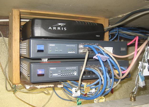
Here the secondary router is between the cable modem and the main. I used the LAN ports that
have the contacts on the bottom first, to avoid those contacts getting dirty from dust.
I used screws to reinforce the wooden crate to be sure it doesn't fall apart
with all this stuff in it. Also found that those pieces of plastic used on loaves of bread make
for easy identification of individual ethernet cables. On the left is a closeup of an ethernet cable showing the pinout colors.
I've since gotten a bigger switch (big blue Netgear box), so the 2nd router above was retired for use elsewhere.
Below also shows a Netgear GS105E 5-port ethernet switch that services an AREDN node thru its POE supply, and there's the cable modem.

Make your own ethernet cat5 cable split/combine circuit


Use this cable at your router
Cat 5 ethernet cables have 4 twisted pairs. But with 100BASE-TX, only two of these, the green pair and the orange pair, are
actually used for data. The other two pairs, brown and blue, are usually not used. However, if you're using 1000BASE-T all
4 pairs are used, and this trick is not applicable. But if you are using 100BASE-TX, and have a long
run of cat 5 cable snaked thru the walls of your place, and need to have another port available at the far end, you can
do this simple trick of putting the brown and blue twisted pairs to work. The two pairs of pairs won't interfere
with each other if you use real cat 5 certified cable. You'll need one split/combine at the router, and another
at the far end to unsplit/uncombine the two ports. To make one of these (double the parts count for the two) you need a short
ethernet patch cable, and a female RJ45 cat 5 connector, preferrably one that comes with a cover, like the one in the picture.
Cut the patch cord in its middle, and trim the wires such that the orange and green pairs extend, and trim off completely the blue and brown pairs.
Port 1's connector's orange and green pairs will go to their respective orange and green terminals on the female connector as usual.
Port 2's connector's orange pair will go to the female connector's brown pair terminals, and the green pair will go to the
female connector's blue terminals. No real reason for this pairing beyond the fact that brown and orange
look more similar than say brown and green. Thus green and blue are more similar looking as well. The cable
in the picture was designed for use at the router (two male plugs go to two router ports, the female accepts
the ethernet cable's male plug (the cable you want to have do double duty). At the far end use whatever combination of male and female connectors
needed to connect the devices to the two ports, using this concept. If the far end ends at a female wall jack, you could
use a male connector insread of the female in the picture, keeping track of which pins connects to the brown and blue
twisted pairs.
Here I used the case of an old DLink box with its 5 jack ethernet connector block (removed off the old
circuit board) wired up to house 5 split/combine circuits. Makes for a neater install.
 Or use a cat 5 connector punchdown block.
 This splitter function could also be done inside a router. Here is an old router that had a dead WAN port. I removed the
bad chip (knew it was bad as it got very hot, along with the lack of WAN function) and the associated ethernet port jack. I then reinstalled the jack upsidedown, to indicate that it
has no connection to the router's circuits. I also cut some traces that tie the pair 1 and 4 to an
RF ground, and connected them to pair 3 and 2 of the upsidedown jack, respectively. The ethernet cable with the
two ethernet circuits plugs into this router's LAN 1 port (which I called "Diplexed jack" in the
picture). The main pair of pairs (3 and 2) feeds into the router's LAN,
as usual. The extra pair of pairs (1 and 4) connects to the upsidedown jack pairs (3 and 2) exclusively, and there
is no connection to the router circuits. Connect an ethernet cable to this upsidedown jack to access the
extra pair of pairs (1 and 4).
This splitter function could also be done inside a router. Here is an old router that had a dead WAN port. I removed the
bad chip (knew it was bad as it got very hot, along with the lack of WAN function) and the associated ethernet port jack. I then reinstalled the jack upsidedown, to indicate that it
has no connection to the router's circuits. I also cut some traces that tie the pair 1 and 4 to an
RF ground, and connected them to pair 3 and 2 of the upsidedown jack, respectively. The ethernet cable with the
two ethernet circuits plugs into this router's LAN 1 port (which I called "Diplexed jack" in the
picture). The main pair of pairs (3 and 2) feeds into the router's LAN,
as usual. The extra pair of pairs (1 and 4) connects to the upsidedown jack pairs (3 and 2) exclusively, and there
is no connection to the router circuits. Connect an ethernet cable to this upsidedown jack to access the
extra pair of pairs (1 and 4).


Below is a method to use an extra or unused LED in the above router to indicate if the cables
to the 2nd ethernet pair and the upsidedown jack are connected. It won't indicate if there's ethernet activity, just
if the cables are connected. As one needs resisters to limit current thru LEDs, here we make them
do double duty to act as high impedance loading on an ethernet signal we will sense for being connected.
Ethernet is a twisted pair 100 ohm balanced transmission line, and extra 1K resistors hanging on it will
be barely noticed. This also limits the current thru the distant/remote device 1's ethernet transformer. I used 0.1uF coupling caps
on the twisted pair inside the above router to avoid
a second DC path thru remote device 2's ethernet transformer. I sense the connection to remote device 2
by looking for the (usually) shorted pair 4 of device 2's ethernet jack. These two things in series
will light the LED (I bypassed with a 0.47uF cap the 1K resistor that goes to one of the wires of the upsidedown jack pair 4 to ground at that jack,
to keep ethernet RF from leaking out
the cable to device 2). Put the resistors right near the active ethernet pair, to avoid stray capacitance, as you would for any RF circuit.

Another method: 
An alternate circuit would pass the LED current thru the green twisted pair's ethernet transformer in
device 2, as well as the green twised pair's ethernet transformer in device 1. Maybe pair 4 in device
2 is open circuit. One side of the twisted pair's wire has a 0.1uF coupling cap interrupting (for DC)
it, located at the "upsidedown" jack. And a 1K resistor to ground, and on the other side of the cap
another 1K resistor going to the LED. And a 0.1uF bypass cap to ground on that line to the LED. And
the other side of the LED goes to a 330? resister and then to 12VDC. The other side of the ethernet
twisted pair has a 510? resistor in series with a 0.1uF cap to ground, to balance the loading imposed
by the pair of 1K resistors on the first side.

A daisy chain style cable I used at the "load" ends. Mildly ugly... On the right above I put the extra
blue and brown pairs to use as a DtD (device to device, vlan2) connection between two AREDN nodes. Make the spices
carefully, I had a poor connection at first that would eventually cause many errors and have one of the ports
decide to disable it ("errordisable" state in the Cisco world), making the DtD link disapear. Having the green and yellow LEDs on an ethernet
jack light up doesn't mean that it's not a poor connection. AREDN
(Amateur Radio Emergency Data Network) is a digital ham radio mesh network using wifi equipment reflashed for this work. See the AREDN web site
for more info.
Using old 10base5 thicknet Ethernet coax for radio work


Just a quick note that if you happen to see any of this stuff at a hanfest, or maybe the IT guys at work haven't gotten around
to throwing it out yet. 10base5, dates back to the 80's, so if your place of work dates back to then, maybe...
Sometimes found under newer cables in trays above drop ceilings. It's just well shielded RG-8/U foam 50Ω coax.
Under the outer jacket is a layer of braid, then foil, then another layer of braid and then under that another
layer of foil atop the foam dielectric.
Orange is teflon. Usually has N connectors, but you can use UHF PL259s on it,
just be careful you don't melt the foam dielectric when you solder it. I usually
have to file off the nickel plating at the shell's solder holes to get solder to wet
it right, without roasting the dielectric. Check the coax for holes where "vampire"
taps were installed. These holes may not much matter on HF, but may be an issue on UHF.
I usually just cut the cable at these holes and made use of the resulting lengths for shack
patch cables and such. I've used long runs of this stuff on HF, and 2 meters, and even some short
segments on 2.4GHz wifi antennas. Attenuation over 100 feet is 0.37dB @ 5MHz and 3.04dB @ 400MHz.
There's a web site that uses mathematical formulas as well as topographic data provided by Google Maps to create propagation maps
like the one above.
http://www.ve2dbe.com/rmonline.html
Now for some pretty basic steps (from N4NJJ):
- Create an account. VE2 is the Quebec Province of Canada. French is the primary language here. Be sure to sign up in English, if you can�t read French.
- Once your account is created, click the �New Site� tab in red.
- Position the pushpin over the desired location of the transmitter. Once it is exactly where you want, it �Submit.�
- It will prompt you to name the site. I suggest you name the site by call, frequency, and street name. This is handy when you run multiple sites. (Think linked repeater systems.)
- Hit �Add to My sites.� This will save it so you don�t have to search the globe (literally) next time you want to create a projection.
- Once you have your site, hit the green �New Coverage� tab.
- Be sure to select the correct location in the �Centre Point� drop down menu.
- Enter the requested data. If you have questions on what certain things mean, check the About Me or visit Don�s website for a more detailed explanation.
- Pay special attention to the antenna heights question. You will need to convert from feet to meters. If not, your maps will be way off. I mean WAY off.
- You�ll be prompted for the specs on the transmit antenna (generally the repeater, but could be your base) as well as the receiver antenna. Keep in mind that some people are using portables which would mean the receive antenna is a rubber duck only a four feet off the ground (if on a belt) or a little bit higher if the user is actively talking/listening with portable by his/her mouth.
- Hit submit.
- It�ll take a few minutes for the computer to complete the calculations. Be patient.
- Once it�s done, you can zoom in and out using the powerful Google Maps platform.
- If you want to save the projection, be sure to hit save.
- If you want to share it on your web site or in an e-mail, a screenshot is the way to go. If on a PC, hit the �Print Screen� button on the computer.
download a VHF twinlead
Jpole antenna calculator MSDOS program
Building a 1 : 1 coax balum for HF use:
Using ferrite material intended for RFI work on ribbon cable,
(which cost me 50� apiece surplus)
Fig 1:
One can build a ferrite core toroid using the above ribbon
cable clamshell ferrite bars. The bars shown here measure
about 2cm wide by 5cm long and 5mm thick. Not critical.
You will need 8 such bars.
Fig 2: Arrange them such as this.
Fig 3:
The flat sides of the clamshells
go up against each other for a tight fit.
And the finished product looks like this with about 15 loops
of feedline coax thru the center of the new toroid. I used
packing tape to hold the ferrite bars together. Better tape
may be needed if it will be outdoors. I taped together the
bars in two sections as seen in Fig 2 so I could place
both sections around the existing loops of coax. Thus
I avoided having to thread coax thru the center hole
had I created the complete toroid first.
Fig 4:
I am now able to load up my
attic dipole antenna from 80 to 15 meters
using the automatic tuner in the above TS440S.
The toroid
keeps RF off the outside of the coax feedline.
Otherwise the tuning can be messed up by such RF running
down the feedline into the shack.
Listening to SCA subcarriers on FM broadcast stations with the TS440S, IC-756Pro and
similar radios:
As the TS440S and IC-756Pro can receive signals all the way down to 30KHz all
modes (AM, FM, USB, LSB, CW), you can "surf" the SCA subcarriers
on the FM broadcast band. Usually found as FM modulation at 67kHz and 92kHz,
and RDS/EAS at 57kHz (use the FSK demod on your rig at about 58 or 59kHz).
Also those of any analog TV stations that might still be on the air, on
their sound broadcasts. These are usually found as FM modulation at
78.67kHz (SAP channel), and a cue channel at 102.27kHz (usually found at some multiple or multiple and a half
of the horizontal deflection frequency).
What you need to do is tap the output of the main FM carrier detector
before the deemphasis circuit in an FM broadcast band radio or TV set.
A cheapie AM/FM clock radio or TV set (if you have analog TV transmissions
in your area) will do at first, one with a wide FM IF
strip is better, so the sidebands carrying the subcarriers don't get clipped.
The deemphasis circuit is usually
an RC low pass filter. One way to "hunt" for this point is to
hook up an audio amplifier to a test probe, and find a node
on the circuit board that has main channel broadcast audio with
lots of treble as compared to that found at the top of the volume
control. If you can't find such, take a look for a small cap (on the
IC pin with the audio demod out) that goes
to ground which in combination with a resistor may be the deemphasis
network. Try disconnecting the cap. One this spot has been identified,
connect a 0.01uF
cap in series with a 1K resistor, and that then in turn feeds
the center conductor of a length of thin coax. The coax ground
connects to the radio ground. The other end of the coax connects
to the TS440S antenna input. Check that the FM broadcast radio
still plays, as the coax cable is now loaded with 50Ω impedance.
If you have an older mono FM tuner like an Eico HFT90, connect to the
multiplex output jack (the one intended to feed an external stereo
demodulator) and use a resistor of around half a meg in the signal
path from this jack to the TS440SAT or IC756Pro receiver. Or use a cathode follower or
emitter follower to lower the impedance without much signal level loss. This will avoid
excessive loading of the normal mono output signal (so you can listen
for FM stations' main mono audio channels).
Below I did this in a Technics STZ780 tuner, and added a buffer emitter follower output circuit.
I coupled a 10uF cap to the FM demodulator chip's audio output (between that and the stereo demodulator chip)
and fed that to the double emitter follower. I used a pair of 22 ohm resistors,
with a pair of 6V zeners and a 0.1uF cap in series to ground in between, for
the 50 ohm output impedance to feed the rig's 50 ohm input. The zeners are an attempt to limit mistaken RF transmit power.
You can see on the Icom 756 Pro's panadaptor display
the SCA's spectrum space. You can see in the lower middle pictures below the emitter follower.
The subboard with the three IF cans is another separate mod
for wide band audio on AM reception.
SCA at 67KHz:  and at 92KHz:
BTW, you can see an RDS transmission at 57KHz in the display in the above left picture.

Disconnect the mic on the TS440S or IC-756Pro so you don't accidentally
transmit into the FM radio! That could happen if, say, you quit listening to SCA signals and
want to get on 40 meters, and you forget to switch from the FM radio to the 40 meter dipole!
Hopefully all that gets fried is the emitter follower...
Tune in 38KHz in USB mode. Now tune around on the FM broadcast
radio. You should be able to hear the "difference" (L-R) audio signal
of FM stereo stations. You should be able to notice the usual
lack of vocals in most songs, as compared to the FM broadcast
radio's mono speaker output. Assuming success, try tuning
in 67KHz FM mode on the TS440S or IC-756Pro. Now tune around on the FM
broadcast radio. You may find various foreign language programs
and data transmissions. Also try 92KHz FM on the TS440S or IC-756Pro.
Expect about 10% of FM broadcast stations to have subcarriers.
If you've tried to build the usual SCA decoders using PLL
circuits or FM demod chips, you know that crosstalk from the
main program material is a big problem, but the TS440 and the IC-756Pro receivers seem much better
handling this problem, as their selectivity and dynamic range are much better. Similar
ham transcievers should also work well with this (again, be sure to disable the transmitter).
Don't overlook the college radio subband from 88 to 92 MHz.
Be aware that some HF rigs may have little sensitivity down from 30 to 100KHz, even if they tune these
frequencies. My IC7300 is quite deaf around here.

SCA signals are about 12KHz wide. The freq divisions above are 5HKz. In addition to the 67KHz SCA subcarrier,
you can see some of the 92KHz SCA
subcarrier on this FM broadcast station, and some of the stereo difference DSB subcarrier.
You're essentially "surfing" the radio spectrum in two dimensions,
one "axis" is the FM broadcast band, and the other is each FM station's
subcarrier signal spectrum.

Yeasu FT227r mod so it cold powers up on your favorite 2M frequency
This is an ancient 2 meter rig, with a PLL frequency synthesizer. Its controller is
just a handful of logic chips, no microprocessor. So it's fairly easy to modify the
frequency it puts itself on when you power it up cold. It came up to 147.00x MHz, x is
a 5KHz offset selectable by a switch.
There's a PLL controller board, with the above logic chips. The
tuning knob is an optocoupler up and down device. The up or down
drives up or down binary coded decimal counter chips. These chips have
preset values the counter uses to set itself when you power the rig up, and
changing these values lets you hard wire a favorite frequency.
Looking at the below diagram, Q707, 708 and 709 are these chips, MC14510B. Pin 3 is the most significant
bit MSB, pin 13 the 2nd MSB, pin 12 the 3rd MSB, and pin 4 the least sig bit LSB. You'll
find most of these hard wired to ground, so some trace cutting or pin lifting on the bits
you want high will need to be done. Binary coded decimal (BCD) are the bit patterns for each digit of your
favorite frequency. The units of MHz (the 14x.000) are controlled by an inverter chip Q710 feeding its
pins 12 and 13, and if you want to change these two presets, just tie the resistor R703 to ground. Doing
just that will move the radio from 147.00 to 145.00 upon power up. Make its pin 4 high to make it go on 146.00. This MHz
digit is BCD encoded after subtracting 3. That's why a BCD 3 in this 1MHz position gives you 146MHz. The 100KHz
digit is normal BCD, the 10KHz
position is also normal BCD.
If you have two favorite frequencies, on on 14x.xx0 and the other on 14x.xx5, you can grab the 5UP switch's 5V side. Work
out which bits always stay low, which always stay high, and which must change for the different frequencies.
Always low, Yeasu already tied them to ground, always high, tie to 5V, and for the ones that will change, I used pull down resistors
of 10K (the chips are MOS chips, so it's just as easy to pull low ans it is to pull high with resistors). I used
surface mount resistors, as they easily fit between chip
pins and traces.
Then connect two wires to the ends of the 5UP DPDT switch, the side with 5V (the other side switches 12V, so
avoid that). When one set of changeable bits that must go low for one of your frequencies, you connect the
other changeable bits that must go high to the switch contact that currently has the 5V (when the 5UP switch
selects x.xx5, this switch contact is the one towards the back of the rig. For x.xx0, that contact is towards
the front of the rig.
My example:
146.955 is (msb is left) 011i 1001 0101 The leading 14 (MHz x 10) is hardcoded elsewhere.
146.790 is (msb is left) 011i 0111 1001
144.390 is (msb is left) 010i 0011 1001 (instead of 146.79, note that the LSB value "i", a 1, of chip Q709 is subsequently inverted, the result becomes a 0)
The bits that differ from one frequency to the other, are the ones that need to be switched. The other bits that
stay the same are hard wired high or low, as needed.

Modifying toy 49MHz AM walkie talkies for 6 meters:
For some super cheap local QRP comm work, modify 2 or more
of those cheap AM superregenative 49MHz walkie talkies
Radio shack or KB or other toy stores sell for less than
$10 a piece. I found a small quantity of surplus crystals at
50.3714 MHz for 79� each. These particular ones look like TO3
transistors, but they fit in the talkies. Of course,
try out the talkies before mods are done. Then replace
the 49MHz crystal with the new 6 meter crystal. Then
using a real 6 meter rig receiver tuned to the new crystal frequency
or a counter, check the carrier frequency when transmitting with the
modified talkie. If you need to, you can adjust the frequency
adjust coil.
See pictures to see what
this coil usually looks like. I used
the above mentioned crystal as it puts me into the "all
mode" subband, where AM is proper. Be sure to mark the
modified talkies as ham rigs, and only let hams use them.


 Recently, 39 years after I graduated, had occasion to pay my college a visit.
The ham radio club is gone, but the outlet I installed back then in a nearby stairway to obtain building emergency power for the club radios is still there!
Recently, 39 years after I graduated, had occasion to pay my college a visit.
The ham radio club is gone, but the outlet I installed back then in a nearby stairway to obtain building emergency power for the club radios is still there!

 To get a pdf of your license that says "Official Copy" go log in at https://wireless2.fcc.gov/UlsEntry/licManager/login.jsp, then on the next
page
click "download electronic authorizations" and you'll get a page where you should find your
license in a box marked "Filter by radio service". Select your callsign inside this box and
click "add" just to the right of this box. Select your callsign again in this
"Authorizations to download" and then click "download" below this box. You should then get a
pop up window asking you to open or save the pdf. You'll now have a printable pdf that says "Official Copy" on it, suitable for framing.
To get a pdf of your license that says "Official Copy" go log in at https://wireless2.fcc.gov/UlsEntry/licManager/login.jsp, then on the next
page
click "download electronic authorizations" and you'll get a page where you should find your
license in a box marked "Filter by radio service". Select your callsign inside this box and
click "add" just to the right of this box. Select your callsign again in this
"Authorizations to download" and then click "download" below this box. You should then get a
pop up window asking you to open or save the pdf. You'll now have a printable pdf that says "Official Copy" on it, suitable for framing.
Build a curtain rod 2 meter rubber duckie antenna


A quick way to put up a small 2 meter antenna to get steady coverage into a local repeater. Using some
magnets salvaged out of old computer hard drives, these mounted to a small piece of metal, about 12 cm long and 4 cm wide (not
critical). A BNC barrel is also mounted thru this piece of metal, about an inch offset from a line that
passes thru both magnets. So you can attach the magnets to the steel curtain rod without the barrel getting in the way.
The curtain rod acts like a ground plane. The rubber duckie attaches to the top of the barrel, and RG58
coax cable attaches between the barrel and the rig, the coax hidden behind the drapes. Of course, the rig
should be low power enough for the rubber duckie to handle. My rig is a homebrew K2ETN built out of Motorola HT220
parts, and a power amp that produces around 7 watts. Back in the 1990's I used this rig on packet.
If you've seen from those days extended TX HT mod files from wa2ise via packet, they likely passed thru this rig on 145.07MHz.
| Ham radio phonetic alphabet |
| Whiskey Alpha Two India Sierra Echo |
| A |
Alpha |
N |
November |
| B |
Bravo |
O |
Oscar |
| C |
Charlie |
P |
Papa |
| D |
Delta |
Q |
Quebec |
| E |
Echo |
R |
Romeo |
| F |
Foxtrot |
S |
Sierra |
| G |
Golf |
T |
Tango |
| H |
Hotel |
U |
Uniform |
| I |
India |
V |
Victor |
| J |
Juliet |
W |
Whiskey |
| K |
Kilo |
X |
X-ray |
| L |
Lima |
Y |
Yankee |
| M |
Mike |
Z |
Zulu |
| 0 |
Zero |
5 |
Five |
| 1 |
One |
6 |
Six |
| 2 |
Two |
7 |
Seven |
| 3 |
Three |
8 |
Eight |
| 4 |
Four |
9 |
Nine |
µΩ°±¼½ >⫩™¯π¾®Ø×÷∅<x²y³©Ω√∞≠Δ≅≤≥

In olden days they used to mark surface mount caps, and this code was used on early SMD resistors (ohms instead of pF's):

Mylar caps have their own scheme. Seems they had to insert letters into their system to include more
voltage ratings. You can easily figure out other codes, like "1D", to mean 20VDC. 2G would mean 400VDC. 3A is 1000VDC

Dogbone resistors from way back (note that they didn't do the log spaced values we use today):


 "A bad day on 10 (meters) is better than a good day at work."
 ,
,  and DigiQSL

 440:
440: 


 Got this one back in 1978,


 My patents


 ALGERIA


 Digital DXCC


 (upper left) to force a true reload.