Old Plastic Tube Radios
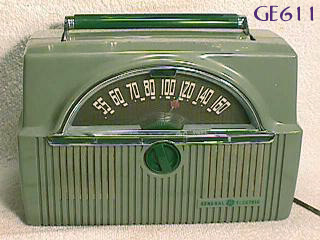
GE C435A


This GE 422 radio is not "rare", it is "well done" :-). A leading consumer journal rated the GE 422 as "very good" back in 1953. It has an RF amp stage, three gang tuning capacitor, and good audio. It is a very good radio, nice DX machine, especially with a 12SG7 tube in place of the 12SK7 in the RF stage and a 19HR6 in place of the 12BA6 in the IF stage.


The GE C415C modified to tune SW from 5.5 to 16Mhz. The dial markings now mean MHz. The first conversion stage produces a 4.545MHz 1st IF. This IF transformer used to be in a TV's sound IF. Then a second conversion converts that to 455KHz. This enables the use of the existing tuning cap and also the dial stays meaningful. The antenna and oscillator coils are 1/100th the inductances of the MW AM radio ones. Thus the 10x boost in frequencies. Better image rejection, but the 5Mhz local oscillator harmonics in the 2nd conversion leaks into the front end. Let's call it a feature: "10 and 15 MHz calibration markers". 
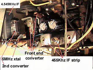
Bypass caps on the heater and B+ to the 2nd converter help reduce this.
The most difficult part of this project is getting the oscillator and antenna coils correctly made and adjusted. First get the oscillator set first. Set the dial to "6" for 6 MHz, and using a reasonably well calibrated SW set (with its antenna input connected to the front end 12BE6 cathode via a 1K resistor) tuned to 6+4.545=10.454MHz adjust the osc coil to that frequency. I used a slug tuned coil form with 12 turns (and next to it a separate 4 turns for the cathode) on it. Now set the dial to "14" for 14 MHz, and adjust the osc trimmer to get the osc on 18.545MHz (again using the other SW set). A few iterations should get both points close on. Now the antenna coil. Using a signal generator set to 6MHz, and the radio set to "6" on the dial (hunt a little bit with the generator) you should be able to adjust the antenna coil (about 20 turns on a slug tuned coil form) to peak resonance. Use the other SW set to verify that the signal generator frequency is close to 6Mhz. Now go to "14" on the dial and turn the generator up to 14 MHz and hunt a bit. Then you can tweak the antenna trimmer. Again verify the generator freq with the other SW set. Iterate a little, and the radio should now be able to tune SW broadcasts.
Being a clock radio (a shortwave only clock radio now, "rare") the power switch is on the clock drive. Easy to place that switch on the "hot" side, and the B- now is directly tied to the neutral power line (assumes a polarized plug correctly wired).