


Old AA5 radios usually don't need new tubes. What *is* required are new capacitors to replace the old wax capacitors and electrolytic capacitors. Ceramics and micas usually don't need to be replaced, though. These old wax and electrolytic caps have lifetimes of maybe 30 years at best. And are at least 45 years old, so.... Replace these caps one at a time, so you won't lose track of where they connect in the radio. I usually never desolder the old leads, as the terminals can be rather fragile. Especially bandswitches (you really don't want to break a bandswitch, as repair or finding a replacement would be almost impossible!). Several possibilities exist: clip at terminals, clip at body of the old cap, or at a point midway between. Clipping at the terminals is reasonable *if* you can easily get in there to solder the new cap in. Be sure to reuse any spaghetti tubing to avoid shorting to something. If the new cap leads don't reach, or you can't easily reach the terminal, the "J hook" procedure can be done, if done neatly. Form small hooks on the old stub, and the new part's lead. Interconnect, and solder. Ideally, the leads should not form a kink, but be in a straight line. Sometimes, if there is existing spaghetti tubing, I'll slip the new part's lead into the tubing alongside the old part's stub of a lead, and at a point where both leads show outside the spaghetti, solder them together. The new cap should roughly occupy the same location the old part was in, especially in high frequency RF areas of the radio.
Be sure to use the same connection points for the new replacement parts, even if one is the ground. Ground loops causing hum can result if another ground point is used. The manufacturer selected suitable points to ground things, and to use other points can cause hard to find problems.
To repeat, do not remove all the caps and then install new ones. You risk forgetting where what went. Better to remove one cap, and install its replacement, one at a time.
Phil has a good web page on recapping radios you could read for more info.
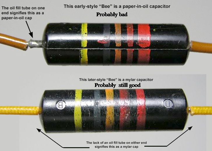
Bumble Bee caps, the old ones are paper in oil, and are surely bad. replace. Newer ones are mylar, so they're possibly still good. See the picture below to tell them apart. The paper in oil ones have a filler tube with a bead of solder on the lead. The mylar ones don't have those.
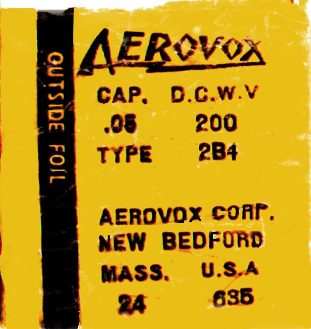
If you want to make the new caps look like old ones, you could take
the below image files, edit the values, and print them out and glue 'em on
the new caps.


Everyone knows you can't solder to aluminum, right? Well,
given the right method, it can be done. The reason it
usually can't be done is there is always a layer of aluminum
oxide in the way. Scraping in the air does no good, as a new
layer of oxide forms in about a nanosecond. The way around that
is to keep air from the freshly scraped aluminum surface. Short
of booking a flight on the space shuttle, this can be done by
a puddle of hot solder over the spot you are scraping. Solder
then can attach itself to the aluminum before the air can get
at it. Use a cheap soldering iron tip for this; *don't* use
one of those fancy plated Weller tips, as it will get ruined
by this process. You should see solder wetting the scrape marks.
After you get what looks like a solder joint,
test by tugging on it to be sure you didn't just glue it with
rosin, but created a real joint. You'll need a big enough solder
iron to get the aluminum hot enough to melt solder. You may need to
do tricks like drilling a few holes around the spot to be soldered
to, to reduce heat loss. Or create a tab. You've seen tricks
like this in circuit boards and steel chassis. �
As the IF transformer caps are adjacent to each other on the
mica wafer, and if there is any overspray of silver between the
two, this can create a leakage path from B+ or plate circuit to
the grid or AVC circuit, or at the detector, introduce undesired
excess positive bias on the diode detector plate.
Symptoms of leakage
can be "thunderstorms" of static from erratic B+ current from
plate LC circuit to the grid LC circuit, and upset of AVC bias voltage
(if it's the first IF transformer) or distortion of weak stations
from some B+ leaking into the diode detector (2nd IF), pushing it into a
region of more conduction per cycle of carrier. Very weak stations
could be completely lost, as their entire carrier waveform is held
positive compared to the detector cathode. Then the diode cannot
do its job of rectifying the carrier, thus no audio signal.
Partial non symmetrical (ie, not at zero crossing)
rectifying of the carrier would yield audio distortion.
An alternative to replacing the mica wafer caps is to
use a sharp knife to scrape away the leakage path, or even
cut the wafer in two between the two caps. This can sometimes
be possible in later circuit board mount IF transformers
of manufacture other than K-tran. If the leakage path is the
problem, this method avoids much disassembly and also you
probably will not need to touch the alignment once you reinstall
the IF transformer back into the radio.
Transistor radios sometimes need recapping too!
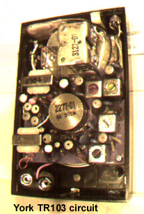

Older transistor radios can have capacitor trouble. Those little
electrolytic capacitors in Japanese made transistor sets can go bad,
usually open. In the York radio above, all the electrolytics dropped in
value to the nanofarad range. Symptoms can be low audio volume, squeals on radio
stations, and such. Audio coupling and or bypass capacitors going bad by going
too low in value can cause low volume and tinny sound. AVC filter caps
going too low in value can cause oscillations in the RF and IF sections
of the radio, as well as bad bypass electrolytics. If the bad caps
have in fact gone almost open, one can check them by touching across
them a good electrolytic cap and see if improvement happens. It is
likely that all the electrolytics, being the same age and manufacturer,
have all gone bad. Might as well replace them all while you have the
set apart. Replace one at a time, and pay attention to which side the
positive terminal goes to. As these old caps had a wide tolerance in
value when made, a replacement can be within 50% capacitance and work fine.
Higher voltage rating is also fine as long as it will physically
fit (which shouldn't be a problem, modern caps are smaller anyway).
Be careful soldering on those Japanese circuit boards
as the glue that holds the copper traces down isn't too good in those
old sets. It doesn't take much to lift a trace. Use a cap to reduce or eliminate RFI from
old fashioned non electronic ballast florescent lights.
 Solder to aluminum? It can be done!

Copper braid soldered to an aluminum heatsink. Scrape the oxide
under a solder puddle.
Here's one that drove me nuts for a while: Bad capacitors in an
IF transformer. Symptoms were intermittent changings in radio
signal strength. This was confirmed by measuring the AVC voltage.
B+ was steady. Volume control set to minimum would remove the
static sounds. So, it had to be upstream of the volume control,
and the detector diode. Bad tubes? No. Bad contact on tube
sockets? No. Plate voltages on the 12BA6 and 12BE6 were
steady. Now, if the capacitor of the IF transformer LC circuit
cuts in and out, that could do it. Spayed some ozone layer
killing freeze spray into one of the IF transformer's bottom.
No change. Did same to the other IF transformer, got some
intermittence. Ah ha! removed the IF transformer, and took
it apart. Turns out that the caps of the transformer's LC
circuits are just silver plating on a sheet of mica. And the
circuit connection is made by a press fitting of the metal
terminal contacts sandwiched between some plastic. If the
contact corrodes.... Intermittent operation. Removed the
rivet that held the cap wafer in there, and measured the size
of the caps. About 100pF. (Another IF transformer I just fixed
used 150pF caps. So make every attempt to measure them before
throwing them out. I tried to solder leads to the silver, no go.
If you can't get a measurement, try using smaller caps and add
more if necessary when the transformer is back in the radio).
I soldered in some real silver mica
100pF caps to the under chassis terminals (easier to change
if you can't get the transformer to peak). Your choice
whether to put the caps inside the IF transformer can, or
down below the chassis. Reinstalled the
transformer, and it needed only some tweaking to be on
frequency of the IF, namely 455KHz. If you can't get it to tweak,
try a few pF more capacitance. I underestimated a little
on the cap value, as it's easier to add than remove pF's.
Operation over a
few hours was steady, no more intermittence. Also,
using
undersized caps will make you adjust the cup cores closer
together thus increasing the coupling factor "k". And yield
a few more dB of gain. Be careful not to overdo it, or else
you will get a pair of peaks with a valley between. You'll
know if this happens, each station will start showing twice
on the dial. Next to each other. Before it gets that bad,
you'll notice distorted audio highs on stations. Because the
carrier strength is lowered too much by the valley. So, back
off by paralleling a few more pF's across the caps.
BTW, if you compare the two IF transformers in an AA5 set,
the more closely coupled IF transformer is a "diode transformer"
and is designed to match the load of the detector.
The looser transformer is
an "interstage" transformer.

 Leakage of current from primary to secondary LC circuits
in IF transformers
Leakage of current from primary to secondary LC circuits
in IF transformers
Unused band going dead from long term lack of use: A tube with
heater hot but without any current draw can eventually ruin
the cathode. If an AM/FM radio was only used on FM, the AM
converter tube (12BE6) may be weak or dead due to this.
A few microamps current is all that is needed to keep the
cathode alive. You can provide this for either the AM or
FM (whichever is not being used) with a resistor of around
a half megohm connected from the AM B+ to the FM B+. You
could connect it right at the B+ switch contacts of the
band switch. When
FM is selected, a few microamps flow thru the resistor to
the unused AM tube, and if AM is selected, current flows
thru the same resistor to the FM front end and other FM
only tubes. This won't fix a ruined tube, but should prevent
new tubes from getting ruined by this.
Pilot light keeps blowing out: In an AA5, the pilot light
is run off of a tap on the heater of the rectifier tube.
This is to compensate for the differing "thermal mass" of
tube heaters and light bulbs. That is, that tube heaters
take longer to light up than light bulbs do. And the
variation of resistances over time differs.
Tube heaters and light bulbs when cold
have less resistance. This is why the
pilot light isn't just in series with the heater string. The
bulb would get overvoltaged and burn out. The section of
rectifier tube heater placed in parallel with the bulb is
to absorb most of the warm up current (which is much higher than
normal operating current) and allow the bulb
to see only the voltage it is rated for. But if the rectifier
tube's tap isn't done correctly, the bulb may still get too much
voltage and burn out. Try swapping from a radio that does not
have a pilot light the rectifier tube. The pilotless radio will
work just fine with the pilot light blowing tube. Also a resistor
of about 47 ohms in parallel with the pilot light should help.
Audio distortion in the output stage caused by a bad circuit
wafer: Usually these are little ceramic resistor/capacitor
circuit wafers. And rarely go bad. But I just had a bad
one. Check the cathode and
grid voltages of the output tube (50C5). Grid should be at
zero, and cathode around 6 to 7 volts positive. If the grid
seems to be a few volts above zero, there is a leakage path,
probably the coupling cap from the 12AV6 plate.
 Typical circuit wafer.
Audio output transformer bad? In a pinch, one can use
a power transformer with a secondary of 6.3V center-tap.
The turns ratio of the 120V primary to 6.3V secondary
is 20 to one. With an 8 ohm speaker as load, that works
out to be 8*(202)=3200 ohms on the primary side,
close enough to the 2500 ohms a 50C5 wants to drive.
Output power will be a dB or so lower, but that will be
not noticeable. If driving a 3.2 ohm speaker, use half
of the secondary, ie, 3.15V. That's from one end to the
center tap. That will look like 3.2*(402)=5120 ohms.
Kinda high, but the output power will be half the original
value. But you'll be back "on the air".
Changing the speaker to an 8 ohm one would
probably be worth the effort here.
The frequency response of a power
transformer will be adequate for an AA5 radio, but won't
be hi-fi.
Bad sound when volume is LOW, seems okay when louder. AA5
radios use a class A audio amp. So it should work fine at
low volumes if it works at louder volumes. If we had a
class AB or class B amp, we could have crossover distortion.
In the case of an AA5, suspect a bad speaker. A small amount
of rubbing in the voice coil could do it. Do this test:
disconnect the secondary of the audio output transformer
from the speaker. One lead is enough. Measure the DC ohmage
of the speaker. Using a similar DC ohmage speaker, connect it
to the transformer secondary. Turn radio on, and listen
to see if the distortion is still there. If not, original
speaker is bad.
Just finished (or so it seems!) an AA5 repair. Symptoms were: low audio,
occasional cracking sound, distortion on strong local stations. This
after doing a re-cap of wax caps. The radio is an RCA 8X541 using octal
tubes, and no graham cracker module in the audio section, but discrete
resistors and capacitors.
Could tell that the crackling was happening before the volume control,
as the sound level of the crackling could be varied, and zeroed, by
the volume control. Tried swapping tubes, not it.
Also used a DVM to measure the AVC voltage, seems kinda low compared to
other AA5's I've played with.
I have a 100MHz o-scope and an isolation transformer, so I got out
the "heavy artillery". With the scope I could see the modulated RF
(actually the IF) carrier in the IF section. Could see clipping on the
strong signals. I could also see rectified RF (if) at the top of the
volume control. That shouldn't be, it should look like a filtered
audio waveform. Could also see spikes correlated with the noise here,
but didn't see the noise spikes in the IF stage.
At this point, the final IF transformer is suspected. I see it has 5
terminals, one of which is grounded. Must be the infamous mica
capacitor problem (leakage to B+, and poor contact). Tried cutting
the ground connection, and problem went away. And the low AVc problem
also went away when I added a 50pF cap from the top of the volume control
to ground (to replace the function of the old cap in the IF transformer).
That took care of the distorted strong local station, and the rectified
IF waveform now looked like filtered audio.
Radio has been playing nicely for the past 1 1/2 hours while I've been
surfing the web and newsgroups on the 'net.
Rattling sounds: Sometimes a mechanical resonance will be
present in a radio set. A rattle sound on loud passages of
music or voice. This can happen when the audio from the
speaker causes a mechanical resonance in some part of
the radio chassis or cabinet (or between the two). This
can be hard to locate and solve. You should get a sine wave audio
oscillator that can be varied to sweep thru the audio range.
This can be an old Eico or Heathkit. Also you'll need an
AM transmitter (or FM if it's an FM only set). Click for
a tube, or
solid state micropower
transmitter you can build for this and other uses.
Find an empty frequency on the dial, tune the transmitter
to that spot. Feed the output of the audio oscillator
to the transmitter to modulate it. Sweep the audio oscillator
to check for resonant rattling in the radio under test.
Try setting the volume of the set to max, but not into
distortion.
This method is actually used in TV production testing to
catch bad TV sets with a rattling defect. If the radio passes this
test, it should do fine on normal program material.
Be aware that this test can be annoying to other people
within earshot!
Correcting the rattles can take a lot of trial and error.
Set the audio oscillator to the frequency where a rattle
occurs. Try tightening mounting screws on the speaker or
chassis. Check sheets of wood or plastic that might be
lightly touching. When you do find and suppress the rattle,
sweep the audio oscillator again to be sure you didn't create
a new problem resonance. This can be a royal pain in the
you know what. Just be careful you don't overtighten screws or
glue down something you may want to take apart later on.
Be sure to check the speaker itself to see if it has any
defects like a tear in the cone, or rubbing voice coil.
Repair or replace accordingly.
Replacing selenium rectifiers with silicon diode or maybe
a bridge rectifier.
Typical circuit wafer.
Audio output transformer bad? In a pinch, one can use
a power transformer with a secondary of 6.3V center-tap.
The turns ratio of the 120V primary to 6.3V secondary
is 20 to one. With an 8 ohm speaker as load, that works
out to be 8*(202)=3200 ohms on the primary side,
close enough to the 2500 ohms a 50C5 wants to drive.
Output power will be a dB or so lower, but that will be
not noticeable. If driving a 3.2 ohm speaker, use half
of the secondary, ie, 3.15V. That's from one end to the
center tap. That will look like 3.2*(402)=5120 ohms.
Kinda high, but the output power will be half the original
value. But you'll be back "on the air".
Changing the speaker to an 8 ohm one would
probably be worth the effort here.
The frequency response of a power
transformer will be adequate for an AA5 radio, but won't
be hi-fi.
Bad sound when volume is LOW, seems okay when louder. AA5
radios use a class A audio amp. So it should work fine at
low volumes if it works at louder volumes. If we had a
class AB or class B amp, we could have crossover distortion.
In the case of an AA5, suspect a bad speaker. A small amount
of rubbing in the voice coil could do it. Do this test:
disconnect the secondary of the audio output transformer
from the speaker. One lead is enough. Measure the DC ohmage
of the speaker. Using a similar DC ohmage speaker, connect it
to the transformer secondary. Turn radio on, and listen
to see if the distortion is still there. If not, original
speaker is bad.
Just finished (or so it seems!) an AA5 repair. Symptoms were: low audio,
occasional cracking sound, distortion on strong local stations. This
after doing a re-cap of wax caps. The radio is an RCA 8X541 using octal
tubes, and no graham cracker module in the audio section, but discrete
resistors and capacitors.
Could tell that the crackling was happening before the volume control,
as the sound level of the crackling could be varied, and zeroed, by
the volume control. Tried swapping tubes, not it.
Also used a DVM to measure the AVC voltage, seems kinda low compared to
other AA5's I've played with.
I have a 100MHz o-scope and an isolation transformer, so I got out
the "heavy artillery". With the scope I could see the modulated RF
(actually the IF) carrier in the IF section. Could see clipping on the
strong signals. I could also see rectified RF (if) at the top of the
volume control. That shouldn't be, it should look like a filtered
audio waveform. Could also see spikes correlated with the noise here,
but didn't see the noise spikes in the IF stage.
At this point, the final IF transformer is suspected. I see it has 5
terminals, one of which is grounded. Must be the infamous mica
capacitor problem (leakage to B+, and poor contact). Tried cutting
the ground connection, and problem went away. And the low AVc problem
also went away when I added a 50pF cap from the top of the volume control
to ground (to replace the function of the old cap in the IF transformer).
That took care of the distorted strong local station, and the rectified
IF waveform now looked like filtered audio.
Radio has been playing nicely for the past 1 1/2 hours while I've been
surfing the web and newsgroups on the 'net.
Rattling sounds: Sometimes a mechanical resonance will be
present in a radio set. A rattle sound on loud passages of
music or voice. This can happen when the audio from the
speaker causes a mechanical resonance in some part of
the radio chassis or cabinet (or between the two). This
can be hard to locate and solve. You should get a sine wave audio
oscillator that can be varied to sweep thru the audio range.
This can be an old Eico or Heathkit. Also you'll need an
AM transmitter (or FM if it's an FM only set). Click for
a tube, or
solid state micropower
transmitter you can build for this and other uses.
Find an empty frequency on the dial, tune the transmitter
to that spot. Feed the output of the audio oscillator
to the transmitter to modulate it. Sweep the audio oscillator
to check for resonant rattling in the radio under test.
Try setting the volume of the set to max, but not into
distortion.
This method is actually used in TV production testing to
catch bad TV sets with a rattling defect. If the radio passes this
test, it should do fine on normal program material.
Be aware that this test can be annoying to other people
within earshot!
Correcting the rattles can take a lot of trial and error.
Set the audio oscillator to the frequency where a rattle
occurs. Try tightening mounting screws on the speaker or
chassis. Check sheets of wood or plastic that might be
lightly touching. When you do find and suppress the rattle,
sweep the audio oscillator again to be sure you didn't create
a new problem resonance. This can be a royal pain in the
you know what. Just be careful you don't overtighten screws or
glue down something you may want to take apart later on.
Be sure to check the speaker itself to see if it has any
defects like a tear in the cone, or rubbing voice coil.
Repair or replace accordingly.
Replacing selenium rectifiers with silicon diode or maybe
a bridge rectifier.


