First, a transistor from Australia: 
Note that Australian radios from the 30's thru the 60's were almost always "stationized".
 ..Pioneer>


 .
.


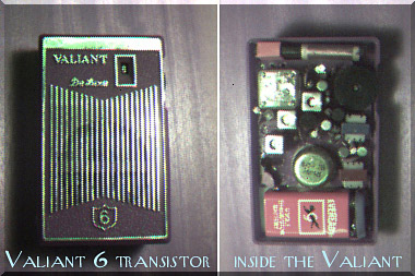
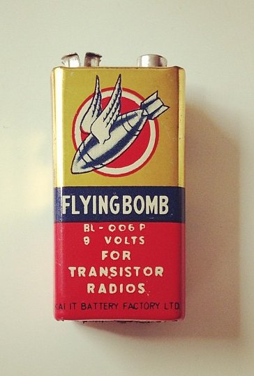 would give me pause before putting it
in a radio, as it may explode.... Leaking battery acid all over.
would give me pause before putting it
in a radio, as it may explode.... Leaking battery acid all over. 


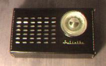


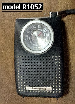
The above center AM transistor is Lafayette #17-0102L,
on the right is an AM/FM set Lafayette #99-3524
 .
.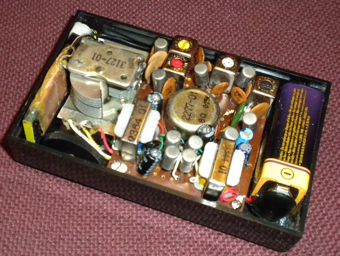
I replaced all the carbon comp resistors (they drift higher resistance out
of spec) with surface mount resistors on the back of the circuit board. The circuit
lands are usually close together enough to allow bridging them with the larger SMD's.
This also makes it easier on the circuit board, as one isn't trying to poke new resistor
leads thru the board. Thus less likelihood of lifted traces. And the circuit paths are
shorter (which doesn't really matter on AM MW radios, but would at VHF frequencies).
Here's the circuit board after this work. Most of the resistors you can't see, as they
are now SMD's on the other side of the board. Below is this back side
(you should be able to spot the SMD's):


The above Lafayette looks just like this above Koyo 10 transistor.
My brother
got the Lafayette new, model FS-129L, mid 60's.

1960:


 .
.


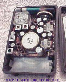
 - Inside Starfire
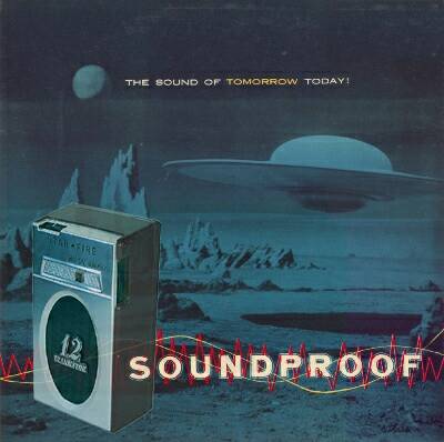
A Starfire 12 transistor radio. All they really did was take a 7 transistor
circuit and added in parallel a 2nd transistor to each of the
original transistors except for the audio preamp stage and the
output stage driver. Thus a "12"
transistor! The converter circuit, 1st IF, 2nd IF, and push-pull audio
output stages all had paired transistors. Base to base, emitter
to emitter, and collector to collector.
This doesn't really add anything to the performance of the
radio as only one of the pair (the one with the lower B-E voltage drop)
will conduct any current and thus do all the work. It was just
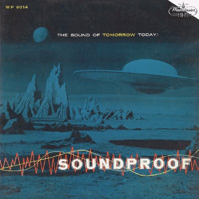
marketing hype. And it looks like they borrowed the album artwork from Ferrante & Teicher's LP record
"Soundproof". Ferrante & Teicher used art from M.G.M. Pictures - producers of "Forbidden Planet"

In the USA, its AM band picks up a few nav beacons, on
its FM band it gets a TV sound carrier.

 .
.

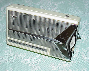
Just like my first radio, the Lafayette #17-0102L above 


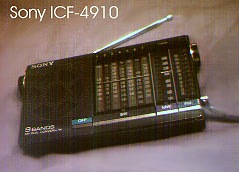
This one above is the 8 transistor version. A converter instead of a
mixer transistor and an oscillator transistor, and only one instead
of two audio driver transistors.

This above radio has an RF stage with 3 gang tuning cap. A good
DXer.
 .
. This radio has my name on it!
  model: 010
