
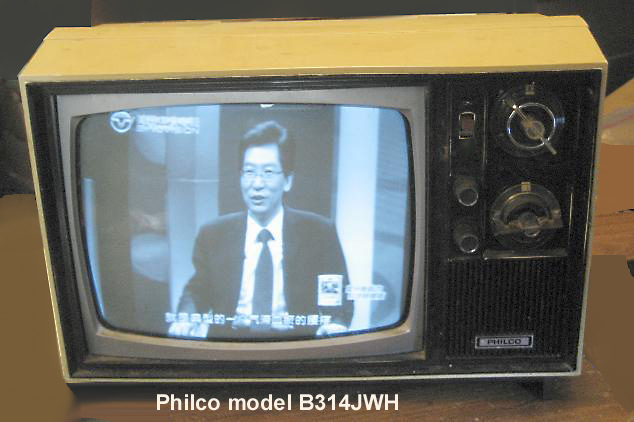
| Televisions |
.
.
.
.
.
.
.


Admiral model 24R12, Diagram

See the Yanks win the Y2K pennant, and then play the Mets
in the Subway Series, on the Admiral set


Careful when you remove the chassis that
you don't drop it and bust off the CRT's neck!


Dial from the TV we watched the first
moonwalk on (Apollo 11).
vacuum tube sets, above,
and right is a Motorola hybrid 


What the Westinghouse set would look like, showing Wilma and Fred Fliststone
smoking Winston cigarettes.
 Back in the days when the NTSC
color TV system was being developed, a test color transmission of some fruit
was done. Some practical joker took the bananas and painted them blue. In the
NTSC color system, the color (more precisely chroma) is encoded onto a subcarrier,
the phase indicating which color. Yellow 180° out of phase yields blue.
The guy at the receiving test site would adjust the phase (commonly called "tint")
to get the bananas right, but then the rest of the fruit would be wrong!
Back in the days when the NTSC
color TV system was being developed, a test color transmission of some fruit
was done. Some practical joker took the bananas and painted them blue. In the
NTSC color system, the color (more precisely chroma) is encoded onto a subcarrier,
the phase indicating which color. Yellow 180° out of phase yields blue.
The guy at the receiving test site would adjust the phase (commonly called "tint")
to get the bananas right, but then the rest of the fruit would be wrong!
 A similar error happened to this weatherman,
who here looks like a Smurf. The chroma subcarrier from the camera looking at the weatherman
got flipped, to become 180° out of phase compared to the chroma subcarrier of the weather map
graphics. Like bananas, flesh tone color (which is close to being yellow) will look blue when the chroma subcarrier is 180°
out of phase.
A similar error happened to this weatherman,
who here looks like a Smurf. The chroma subcarrier from the camera looking at the weatherman
got flipped, to become 180° out of phase compared to the chroma subcarrier of the weather map
graphics. Like bananas, flesh tone color (which is close to being yellow) will look blue when the chroma subcarrier is 180°
out of phase.


 This
This  is not its remote, but it went with
 Marketing named it the "Symetra",
FD498R, included a luma-chroma comb filter with
vertical peaking (marketing called it a "Dynamic Detail Processor"), fake stereo "Dual Dimension Sound" feeding speakers on both sides of the CRT, and
a PLL tuner.
Marketing named it the "Symetra",
FD498R, included a luma-chroma comb filter with
vertical peaking (marketing called it a "Dynamic Detail Processor"), fake stereo "Dual Dimension Sound" feeding speakers on both sides of the CRT, and
a PLL tuner.
Back in the its day, a co-inventor Hermann Weckenbrock and myself at RCA Labs, and proof of concept equipment we built to
show how well our NTSC chroma-luma frame comb separator worked. We used modified CTC121s
that accepted what we'd call today S-video (or maybe it was Y Pr Pb, or RGB, been a while, someone else built the chroma demod and
color matrix circuits, I did the frame comb filter with motion correction) as displays. You can tell from my skinny tie that this was in the 80's.
Today all this roomful of stuff would
fit inside a chip in a smartphone.


 ,
, 


Apex AD3201.
This DVD player has a hidden menu.
To access:
Eject the tray, then press the numbers 8, 4, 2, then 1
on the remote. Dashes should appear on the screen for
the first 3 numbers, then the hidden menu should then appear
upon pressing the last number. Use the ^ and v keys on the
remote to select "region" or "macrovision". Use "enter"
to step thru which region you want (9 is "all" or "bypass") and if you want macrovision
or not. Macrovision may make some vintage TVs or VCR channel modulators unhappy.
To save the settings, close the disc tray. You can now use the "Y" video output
to feed a B&W TV set via a VCR, as it will not have the color subcarrier and
macrovision on it.


 HDTV antennas?


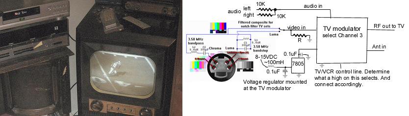
On a vintage color TV, they didn't have comb filters, but only "notch" 3.58MHz bandstop and bandpass
filters for chroma-luma separation. This assumed that anything above 3 MHz on the demodulated
composite video signal belonged to the chroma subcarrier. Problem is that any fine detail in the
luma ends up as crawling rainbow colors on the CRT. Later low end color TVs also did this.

But, if I have a source of S-video (separate luma and chroma, like on a better
HDTV converter box or cable box), I can prefilter the luma (bandstop) and prefilter
the chroma (bandpass) so no fine detail luma exists anymore,
and thus won't become crawling rainbows on a vintage, or a later production notch filter TV set.

The circuit: 
Frequency and group delay responses:
The values of the parts are not that critical. The resulting prefiltered composite
video then feeds a TV modulator to send to your vintage color
TV set.
Your set will present better looking pictures.
 Feeding a VCR with this prefiltered composite video, for recording, will
make for better looking videotapes as well.
Feeding a VCR with this prefiltered composite video, for recording, will
make for better looking videotapes as well.
If I owned a TV station in the 60's and 70's (before comb filters were used in consumer TV sets) I would have done this prefiltering in the equipment that encodes the chroma and luma to become the composite video before it's transmitted. "Football games always look better on your station", fans might have said.
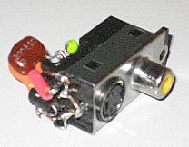
I used a combo composite and Svideo jack I salvaged out of a dead DVD player to build this filter on. The cap lead with the red sleeve here is the chroma.


Had an older RCA XL100 TV set that used a mechanical click twist tuber (not a varactor or
synthesized tuner). And had an extra Channel Master CM7000 CECB with S-video output. I decided
to make this TV into a digital ATSC receiver by removing its old tuner and installing the CECB
inside it. What this would do for me is to create a color TV set with no cross luma cross chroma
defects (no false color crawlies on fine luma detail, and no crawling or hanging B&W dots on color
transitions in the video image). What I worked hard at the RCA Sarnoff labs to reduce with the then broadcast
analog NTSC TV signals. As the Channel master CM7000 provides S-video outputs (the luma and the chroma
never having been merged together, thus no cross signal defects later). Downloaded the SAM's ($22 but was
worth it to find my way around the TV circuits) and found the points to inject the S-video and the
notch filter on the luma I'd want to remove. I did not use termination 75Ω resistors on the
luma and the chroma signals, as the unterminated voltage levels are close to what I
need, and any reflections off the unterminated coax ends would be absorbed by the source 75Ω
resistors inside the CM7000. AKA "source termination". Paid attention to be sure the demodulated chroma would
match the luma on the display screen CRT. I used a variable 0-317nsec video delay box to determine that
I need an additional 90nsec delay on the luma. Seems the IF strip group delay response provided this before
I modified this TV set. Also had to figure out how to get the audio into the sound
IF demod and audio amp chip. To avoid deflection buzzes in the sound, I used an audio isolation
transformer to break a ground loop (and carefully located and positioned the transformer mounting orientation for minimal
deflection noise pickup).

Luma delay test setup to match chroma, 
placed between the CM7000 and the CTC108 circuit board (the video line driver circuit is to buffer the
delay line from the unterminated feed to the CTC108 board)

And just got the 30nSec 100Ω analog delay lines. 3 of them in series gives me 90nSec of delay.
The delay likes are 100Ω impedance, so I added a 24Ω resistor to the video source to make
the video be 100Ω. The few inches of 75Ω cable from the CM7000's S-video jack to this circuit
is of no consequence. And the
delay lines terminate with 100Ω, then the video buffer line driver makes it 75Ω
impedance again.
And what this buffer/delay line board looks like  (I mounted it on the back of the CM7000).

More screen shots showing a lack of cross chroma, below a pattern on the collar that gets cross chroma with a line comb:


And below left is a football game down line graphic (green-yellow-green transitions), and right the football captain symbol
on the uniform (blue-yellow-blue transitions), showing that the
chroma-luma group delay timing is reasonably correct.


The CTC108 chassis is a "hot chassis" design, and here the CM7000 CECB becomes "hot" as well, so I used a special antenna RF coax connector that stops DC and low frequency AC, one designed tor this purpose ("hi-pot"), but lets pass 50MHz and above from the antenna to the box (which is now "hot" inside this modified set).
