These are mods I did with a GE solid state table radio, like their model T1290A.
A better AM detector, an AM RFI filter for its power feed, and a better FM front end, using a JFET in place of a bipolar transistor.
For good FM strong signal performance, ie, better FM receive dynamic range, ie, a better intercept point. avoiding intermod products.
Further below, I added an AM RF stage to this radio.


 This homebrew set, now a "23 transistor", above uses a GE circuit board
almost identical to that in the GE T1290A. Right click "view image" to see the schematic, with my mods. full size.
To improve the FM front end, I changed a grounded (with respect to RF) base bipolar
transistor (BJT) to a grounded gate JFET (green in this diagram),
a 2N3822, in the FM RF amp stage. This is to
improve the RF stage to have good strong signal performance, ie, better FM receive
dynamic range, ie, a better 3rd order intercept point. avoiding intermod products.
This homebrew set, now a "23 transistor", above uses a GE circuit board
almost identical to that in the GE T1290A. Right click "view image" to see the schematic, with my mods. full size.
To improve the FM front end, I changed a grounded (with respect to RF) base bipolar
transistor (BJT) to a grounded gate JFET (green in this diagram),
a 2N3822, in the FM RF amp stage. This is to
improve the RF stage to have good strong signal performance, ie, better FM receive
dynamic range, ie, a better 3rd order intercept point. avoiding intermod products.
The third-order intercept (TOI) point is a measure of the linearity of a device,
such as an amplifier or mixer. It is defined as the input power level at which the
third-order intermodulation distortion (IMD) products are equal in amplitude to the
desired signal.
JFETs typically have a high third-order intercept point (IP3) compared to other
types of transistors such as bipolar junction transistors (BJTs). This is because
JFETs have a more symmetrical transfer characteristic and lower input capacitance,
which reduces the amount of distortion repersented by third-order intermodulation.
I selected R1 to self bias the gate (about half a volt
negative compared to its source) to approximate good bias.
The JFET, running at a similar amount of current of the old BJT, will likely be more linear than that old BJT
and that gives a better intercept point. JFETs also have low noise characteristics, which is
critical for FM front ends
because noise can degrade the signal-to-noise ratio (SNR) of
the receiver.
The old NPN BJT device likely had low enough noise, but running it
at low current (for high gain), yielded possibly slightly better gain, but more seriously,
definitely a poor 3rd order intercept point.
You'd want better 3rd order intercept point if you live near New York City, with its crowded FM dial (see below).
The JFET also has a low noise figure and decent enough gain. You could increase the current thru the
BJT to improve its dynamic range, but the noise performance would be worse than the JFET.
And the mod would also need substantially
different circuits to get beyond that, much more mods than I wanted to do.
I also tried other JFETs, a 2N5458 with a 180Ω. or MPF102 with a 220Ω, source
resistor, and got results pretty much the same. I kept the 2N3822, as its data sheet states that it's for VHF work, and it seems just noticeably better.
And here is a method of checking your junk box JFETs.
 NYC's crowded FM dial. Below
the before and after of the FM front end:
NYC's crowded FM dial. Below
the before and after of the FM front end:


FM fool's predicted NYC dial:
One version of the new FM front end uses a VHF TV set balun. But the JFET will see everything in the VHF spectrum.
Another version uses an LC circuit tuned to around 99MHz. One turn of insulated wire forms the
input from the FM antenna terminals but isolates the antenna terminals from the hot chassis shock hazard. Only thing here is that the radio will be
less sensitive at both ends of the FM dial. Using a pair of LC circuits (one around 91MHz, the other around
105MHz) coupled via induction and stray capacitance to give a reasonably flat band pass over most of the FM dial helps here.
Using a grid dip meter helps a lot in getting these LC circuits on these frequencies.
I used a single ferrite adjustment slug mostly for the 91MHz LC circuit, I had to fiddle with trim caps to
get both resonances where I wanted them. The single ferrite slug helps couple RF antenna energy
across the LC circuits and into the RF amp stage. You can check the grid
dip meter's calibration by seeing what its dial says when you jam an FM station of known frequency.

Closeup of the FM front end's input and band pass filter. The LC circuit further from the circuit
board is peaked around 105MHz, the closer one 91MHz.
Antenna coupling is an almost single turn of wire
fed from the antenna terminals.
Maybe this makes it around 300Ωs? Probably too short to matter. Reception is slightly better
than that I had with the input balun. The curve is just a guess, stations around 98MHz come in
pretty well, so they are likely just "couple o' dB" down.  Sure, it might
be better if I had a 3rd FM tuning gang on the tuning cap, but I don 't... (but see further down this web page).
I did try a tuned circuit on the FM RF amp's input (built it with a grid dip meter to get its frequency
range correct) with an independent tuning cap, but it didn't seem effective, about a db at best.
Not worth the trouble of mechanically rigging it to the tuning dial.
Sure, it might
be better if I had a 3rd FM tuning gang on the tuning cap, but I don 't... (but see further down this web page).
I did try a tuned circuit on the FM RF amp's input (built it with a grid dip meter to get its frequency
range correct) with an independent tuning cap, but it didn't seem effective, about a db at best.
Not worth the trouble of mechanically rigging it to the tuning dial.

The modified radio, with replacement resistors and electrolytics. And note the white wires with orange and blue (Syracuse!) colors on the tuning cap.
Adding an FM input LC tuned circuit, And the mechanical construct to couple it to the rest
of the tuning caps

The main difficulty in adding a tuned LC circuit on the input to the FM RF amp is to mechanically
couple it to the rest of the radio's tuning mechanism.
Obtain another AM FM tuning cap and use its FM RF section, and ignore the FM osc and the AMs.
Initially, I mounted the new cap coaxially
with the existing tuning cap. And I used a long screw to act as a pin attached to the new cap
that in turn fits into a new hole in the tuning wheel mounted to the existing tuning cap. So
when the radio is tuned, this pin also makes the new cap also get tuned. A kludge, but it
worked reasonably well. I then decided on a more elegant method, mounting the new cap to the existing piece of
circuit board I mounted the tuning knob to. And using a pair of same size tuning pulleys
and dial string to couple it to
the main existing tuning cap.
Looking at the bottom of the "new RF amp" schematic above, you can see the new FM front end
RF amp input LC circuit. With the new variable tuning cap "C1K" (with its own trimmer C1M, and the
coil LN are adjusted using a grid dip oscillator (GDO) to have it track the existing tuning cap.
Tune in a station near the bottom of the band, tune the grid dip oscillator to "jam" that station, and adjust
trimmer C1M to get the new LC circuit to resonate (which is when the GDO dips). Do that with
another station midway in the band, and another near the top of the band. and iterate a
couple of times. And adjust the inductance of coil LN a little, by spreading or squeezing the
turns. The GDO's dial may be off, but jamming a station tells you you have the
desired frequency dialed up on the GDO.
A grid dip oscillator meter.

FM station signal strengths increased on the FM band after I was done. I could adjust
the trimmer C1M and see, with this
signal strength indicator tweak a peak in signal (easier to see with the station just
barely strong enough to dimly light the indicator) at a few different spots on the FM dial.
It can be hard to hear any difference except on really weak signals, which would ask the question as to why bother?
Now that I have a second AMFM tuning cap in this radio, I figured I could build an AM RF amp stage.
The existing AM ferrite rod antenna L5 LC circuit would stay as is, but its secondary
winding would be disconnected from the AM converter transistor. And now it feeds the new AM RF
amp stage (the cyan transistor in the diagram near the top of
this page). The AM RF transistor's collector feeds a new RF transformer,
and its secondary now feeds
the AM converter. I took an AM 455KHz IF transformer and removed its capacitor. The ferrite
rod antenna's inductance measured to be 590uH, and I was able to adjust the full primary of the transformer to
the same inductance. I also checked the AM antenna tuning cap C1A, it maxes at 150pF, and the
new tuning cap C1R also is the same. So this new transformer and the tuning cap C1R should resonate
on AM stations, once the trimmer C1T and transformer slug are tweaked. AM RF amp stages can
be hard to tame, I first ended up selecting a rather small emitter bypass cap of 100pF,
but the impedance of this would vary from one end of the band to the other by a factor
of 3. I did a frequency insensitive feedback loop using resistors in series with 0.1uF caps.
These caps, very low impedance here, are mainly to block DC to avoid messing up voltage biasing. The resistors, 51Ω
for the emitter (not really part of the loop) and 10K from the collector back to the base.
These resistors keep the gain of this RF stage reasonably constant across the AM band. I had this loop
surrounding the tuned stage, but I realized "DUH!"
 that would reduce the selectivity of that
tuned stage... I then made this loop encompass the transistor only. I
selected these resistors by trial and error mainly to get amplification without the stage going
into oscillation. The collector resistor had the bigger effect.
that would reduce the selectivity of that
tuned stage... I then made this loop encompass the transistor only. I
selected these resistors by trial and error mainly to get amplification without the stage going
into oscillation. The collector resistor had the bigger effect.
I used small
coax cables to feed this AM RF amp from the ferrite rod antenna, and another coax cable to feed the
AM converter the AM RF amp's output. And I used one shield to deliver the AM switched positive supply
to this amp, and the other shield the negative ground return. Another short wire connects this
stage's RF ground to the tuning cap's RF ground, via a coupling cap, to keep the LC resonant
currents local.

This diagram also shows the
JFET
AVC assist and received bandwidth circuits (yellow in the diagram above and the one near the top of
this page).
These help keep the strong stations from distorting.
AM MW propagation was good just before sunrise today (Oct 1, 2019), but I didn't expect to hear a station from Syracuse
(my college town!) WFBL 1390KHz, but I did! "The Dinosaur". Never heard any station from Syracuse
in New Jersey before!
Though I get birdies worse on the 2nd and third harmonics of the IF frequency (from
the detector). Not surprising as the radio is more sensitive to signals and noise
and stray from the detector.
I substituted germanium transistors (with base shorted to collector) for the orginial germanium diodes
in the FM detector circuit. These transistors are Texas Instruments house number 102E PNP's, salvaged off old IBM
SMS computer cards. Mostly simple logic circuits, with time delays at worst 40usec. These transistors
would be fast enough for 10.7MHz work. Be aware that many germanium transistors will be too slow, and
you won't get any detection. Maybe the sharper diode knee of these base-corrector strapped
might improve weak signal FM reception I thought, but
I can't say it really had any effect. Oh, the detector worked as well as before, but I can only suspect
a slight improvement. Not really worth doing... This transistor's collector is connected to the case,
and I bent the base lead to solder to the case. This leaves just
two leads to connect to the radio's circuit board. Try to arrange the circuitry so the case and collector are at
an RF ground, and be careful the case doesn't touch an IF can or wire lead or such.


Added an "S" meter to this set. For FM, I tapped the IF strip to measure the amplitude
of the IF signal. FM in this radio does not have AVC, as the FM detector wants the signal to be clipped,
or "limited". So the rectified IF amplitude indicates signal strength. For AM, as there is AVC, the
IF signal level doesn't vary much because of the AVC action, I used the AVC voltage to change the
bias (indirectly, via the transistor (the yellow 2N2222 in the
diagram above and the one near the top of
this page)that drives the attenuation FETs)
on the S meter transistor (yellow green in the diagram near the top of
this page) to indicate AM signal levels. Used a blue LED as a zener diode
of sorts, to make the small variation of this indirect AVC voltage more pronounced on the bias of the
S meter transistor (the FET drive voltage varies from about 4.2V for low signal to 4.6V high signal
level, subtract this "zener" voltage to make this change become 1.6V to 2V, a bigger change in bias
current that this transistor will see, thus making the S meter show a bigger variation).
In FM mode, the source of bias gets switched to one that's constant.
Used the blue LED and a diode to effectively
switch the bias of the S meter transistor between AM and FM modes of operation.
The unselected mode's bias source drops to near zero voltage, so the diode and
LED switches the S transistor to the active mode bias. This circuit doesn't tolerate
power supply variations well (before I thought a barely noticeable loss of gain
on a favourite but weak station after the set was on a
while was happening), so I tried a zener diode to stabilize the supply.
Problem with that is that zener diodes are noisy, and put a lot of hash
into the AM band. One scheme GE used was to use a transistor with its base and
emitter biased backwards, creating a zener-ish voltage around 6 to 10V.
The NPN transistor structure can be employed as a surface Zener diode, with collector
and emitter connected together as its cathode and base region as anode. In this approach
the base doping profile usually narrows towards the surface, creating a region with
intensified electric field where the avalanche breakdown occurs. This may be in the device
data
sheet as Emitter to BASE Reverse avalanche voltage. More usually they quote a lower voltage for
reverse e-b voltage that they imply you should never to exceed.
The emitter-base Zener diodes can handle only smaller currents as the energy is dissipated
in the base depletion region which is very small. It seems to be fine with 7ma. Hand selected a
transistor (the orange one in the diagram near the top of
this page) to give me the desired voltage of 7.8V, and way less noise. The transistor
I ended up selecting is a 2SC1921, a Silicon NPN "Triple Diffused" transistor, It's a
bigger transistor that can do 600mW in normal circuits instead of 300mW, but don't go anywhere near that
much in this zener mode (as the energy is dissipated in
the base depletion region which is very small.)! The bigger
transistor should be more stable, as its base depletion region shouldn't get as hot.
But once you avalanche them as zeners do not use them
as amplifiers The NF of the transistor will be far higher
afterwards.
A bit of a kludge, though...
The gain on that
favourite weak station is now steady, and so is the S meter.
I changed the half wave rectifier in this set to a bridge. Lower ripple. But I had to double
the resistance of the old 230Ω series power resistor R43 to a new one of 464Ω 10W.
Else the B+ voltage will be too high. The reason for this resistor change is that the
filter cap gets to top off its charge at 120Hz rate instead of the old 60Hz rate. And thus
each topping off takes half the current as before. Simulation shows that the resistance of R43
should be doubled to
compensates for this reduced current, thus yielding the same B+ voltage. I had some confusion
here, not realizing that the battery in my DVM needed to be replaced, Before that replacement,
the measured B+ read higher than it really was... DUH!

Note that the ripple on the B+ is about 1.7dB lower with the bridge then that of the half wave rectifier,
However, one needs decent shielding at the volume control's power switch. Else you could get hum. Plastic
shelled power switches are not as good as metal cased ones.
Seems I had the high voltage B+ a little too high. The set tended to motorboat (low frequency oscillation)
after getting warm after about 20 minutes. Also I'd get some popping noises when turning the set off (which
I was blaming on a dirty volume control pot). Figured an electroytic cap has gone a bit leaky, upsetting
biasing. Changed them all on the audio and power supply section, not the answer. I also
changed the electroytics
used for audio coupling C38 and the tone control one C40 to poly film (much less likely to leak).
Shown in reddish brown on the above
schemetic diagram. C39 and C42 were ceramic (usually never get leaky, but are said to be poor choices in
audio circuits, because ceramic tends to be piezoelectric) to films. None of this
really helped the motorboating issue, but
what did help was lowering the B+. Seems I had it a little too high.
I lowered the B+ by increasing the resistance
that feeds the rectifiers from the powerline by an extra 536Ω.
I did this by using a pair of 500Ω power resistors
(one marked by the reddish brown *) to also give me a little more RF isolation from RFI that might be riding in
off the powerline (to 250Ω impedance). On FM, the inductance in the power resistor windings
is about 35uH each, or about 17uH with both in effective parallel. That would yield about 10K of impedance at 100MHz, or 100Ω
at 1MHz.
Though the Q of these inductors would be rather poor, as these were made to be resistors, not inductors.
I figured out what resistance to add by
playing with a Variac, I found a sweet spot for incoming powerline voltage
to avoid the motorboating, and at a maximum of audio clarity and amplitude.
And no popping noise when switching the radio on or off. It plays for several hours and behaves itself. and
it also plays well after being off overnight (after it cools completely).
I checked the voltage feeding the tuner and IF sections, and that was about the
same as before.
Additional mods I did include a separate AM detector
using a base-collector strapped transistor (purple in the diagram near the top of this page, do a "view image"
in Firefox to see it big) for better weak signal demodulation, an
RFI filter
on the incoming powerline.
Inside this homebrew set is the RFI filter, and series resistor. 

This RFI filter knocks down crud from the powerline. Note, right of the power resistor, the white wire with orange and blue, like Syracuse Orange and Blue.
If you are working on GE radios like this, check
the carbon comp resistors. I had to replace a 100Ω, a few 150Ω and a 220Ω
resistors. They all went flakey. The bad 100Ω resistor made the FM local oscillator quit at
the lower end of the band. In a few spots, where the circuit board nodes were close together, found it easier to
use the larger sized surface mount resistors to replace the old resistors that were in crowded areas on the component side of the board.
While you're at it, check the rest of the carbon comp resistors, most in my radio went high by 20 to 60%. I decided to change them all out.
After replacing them, the radio got more sensitive, like I remember it when it was nearly new. The resistors
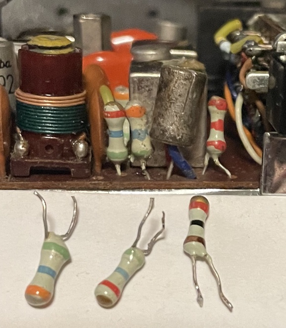
in the green RC circuit modules (some examples below) have held up very well, not drifting in value. No need to change those out.
These in the picture came from other GE radio circuit boards. My father used to get these boards from some
surplus shop on New York City's Canal Street back around 1970.
The audio output transformer has an impedance of 3600Ωs, to 3.2Ωs. If you need to replace it, one made for vacuum tube outputs should work fine.
You may need to mount it elsewhere, but audio isn't fussy about that.
Tube: 
 Transistor
Bipolar transistors, in common emitter mode, have curves that look a lot alike to,
in common cathode mode, vacuum tube pentode curves. So the
output transformer won't notice which device is driving it. Only fundamental difference is that
the transistor has a varying control current instead of the pentode tube's varying control
voltage, which the output transformer won't know or care about. Here we normalize (make the same) the collector
and the plate voltages and currents shown in the above diagrams when talking about this. This
radio uses an output transistor that uses collector voltages usually seen by tubes (ie, around 90VDC).


Above left: unusual resistors, "upright type", essentially single ended. Likely to sub
for regular resistors that would have one lead folded over to have them stand up vertically on a crowded circuit board.
They look like the sort you find in Japanese transistor radios, except these have both leads at one end. Usually, to mount an
ordinary resistor vertically, you have to fold over one of the leads to run parallel to the resistor
body to get back to the circuit board. The pictured resistors look to be a reasonable answer to
this, don't know why these didn't become an industry standard. Look to be designed for use in crowded circuit boards.
That pesky lead on the top is not exposed. These resistors look to be made
using hollow ceramic tubes with resistive material on the outside (under the paint), and one of the leads
passing through the hollow tube center and terminating at the top, and the other lead terminated at the
bottom dogbone resistor style. Then they were dipped to coat them with the paint and then markings. Used a
few of these in the above radio. The Poly Paks ad for these, around 1977.
The green RC circuit modules, upper right.
 One of these upright resistors in my above homebrew GE T1290 AM/FM set.
.
One of these upright resistors in my above homebrew GE T1290 AM/FM set.
.


Above left is the cabinet my radio circuit board was intended to live inside. Center is a National T63 set that used
upright resistors like mine. Right is in an Electra CB-16R single channel CB radio, see the 2K2 resistor on the board. The 56K, 5K6 and 1K resistors
are also uprights pulled off another similar unit.
 Speaking of resistors, they made 1/8 watt carbon comps.
Go easy with the soldering iron or dissipation on these, else the heat will cause the resistance to go up,
making them go out of tolerance.
Speaking of resistors, they made 1/8 watt carbon comps.
Go easy with the soldering iron or dissipation on these, else the heat will cause the resistance to go up,
making them go out of tolerance.

I found a back from a LCD VGA monitor that fit perfectly (horizontally) the wood cabinet I built back
in high school. To replace a rather crudely made back I had before. And used an Orange (for my Alma Mater Syracuse!
BSEE 1978) power cord I had. Turns out I can occasionally
receive (weakly) an AM station WFBL Syracuse here in northern New Jersey.

I did the AM RF amp mod to another radio, and it worked just as well.
Also added the FM input LC circuit mod, and that worked too, though I didn't change the bipolar transistor to an FET.

I was able to acquire an actual GE T1290 radio. Wasn't in working condition, but replacing all the
electroytic caps and the carbon comp resistors got it working nicely. If the circuit board lands
were close enough, I used surface mount resistors as replacements. One ceramic cap also needed
to be replaced; it was making noise on FM by making the FM local oscillator change frequency. This
changing essentially FM modulated FM stations with bursts of thunderstorm noise.


I haven't done any mods to this radio yet. Lots of room inside.
Now I did: 
Did the FET variable bandwidth and AGC assist circuits, and the AM RF amp. Yes, I stole the
RF amp out of a previous radio (one set above this one in this page). With this done, this
radio heard WGR 550 Buffalo here in northeast NJ, also WFBL 1390 Syracuse "The Dinosaur" 3/23/2020.
 Also used the tuned FM
input circuit, and used a J211 JFET as the FM RF amp. Removed R3, 33K, but kept the RC-1
green RC circuit module, Bypassed its pin 1 to ground with a 0.04uF cap.
Also used the tuned FM
input circuit, and used a J211 JFET as the FM RF amp. Removed R3, 33K, but kept the RC-1
green RC circuit module, Bypassed its pin 1 to ground with a 0.04uF cap.
GE badged radios like the T1290 as "Musaphonic", mine just says "Solid State".

Yet another mod, this is a bigger audio output transformer
I changed out the audio output transformer for a larger one, this should yield more bass, and
depending on the quality of the transformers, sould make the radio sound better. Using the
method using an LCR meter described here I was
able to determine the impedance of the old transformer, and pick out a replacement with close to
matching specs. Below you can see the sizes of the new OPT vs the old one.

You can see the new OPT's red and blue leads connecting to the spot the old OPT used to occupy on
the circuit board. Below a top view of the old OPT on the circuit board:

The DC resistance of the new OPT primary is about half that of the old one, which
means that the output transistor will see a little higher voltage on its collector. Transistors in this
circuit will act like pentodes, so this higher voltage will have little impect, except getting a little
warmer than before. Subjectively, the sound quality is now better. "Musaphonic".

Here I changed the audio electrolytics to poly film caps. To improve the audio fidelity of the audio amp
of this radio. Film poly plastics are said to be better than electrolytics or ceramics for audio
work (don't know about polyunsaturated ones though).
I think the sound improved, though I could be wandering into "audiophool" territory... One
cap is the red WIMA MKS 10uF
box, and the other is a yellow WE 3.9uF cap. You can see these in the above picture.
Both are audio coupling caps, the WIMA couples FM demod audio
to the AM-FM band switch and then to the top of the volume control, and the yellow one couples the volume control wiper
to the audio amp input transistor. There's a few more films involved,
see the schematic diagram
way above in the brown highlighted area. To make the audio level of FM be about the same as AM
I added a 47K resistor to be in series bwtween the AM/FM switch and the FM descrimitor detector circuit And
the above mentioned 10uF cap. As the radio sounded a bit shrill, I added a 1500pF poly cap to
grouund as well to attenuate some of the FM audio high frequencies..

 Using a red-green-blue common anode LED light stick
from an HP photo scanner/printer as a dail light, which changes
color depending if AM (yellowish green (some red with green, no blue)) or FM (cyan (blue and green, no red)) is selected.
The green is always on, if AM is selected the red is turned on,
if FM is selected blue is turned on. As the AM/FM switch power section switched the positive
supply, I ended up using transistors to light up the desired LEDs in this common anode light stick.
See upper left in the schematic ("Dial light", red shaded transistor and ble shaded transistor) at
the top of this page.
This stick is longer than the dail, but I didn't need to shorten it.
Besides, there is a mirror of sorts at the far end, to reflect and distribute the light more evenly.
I mounted this light stick to the inside of the cabinet about 5cm above the dial window, to get reasonably even lighting of the dial, and
to avoid fouling the dial pointer mechanism. A long cable with a small connector connects the LED
light stick to the radio circuitry.
The light stick uses red, green and blue LEDs, common anode. The LEDs light up bright enough with
about 2ma DC current each, and with all three LEDs with current like this, will burn about 30mW. Should
be more than low enough power for safe operation.
Using a red-green-blue common anode LED light stick
from an HP photo scanner/printer as a dail light, which changes
color depending if AM (yellowish green (some red with green, no blue)) or FM (cyan (blue and green, no red)) is selected.
The green is always on, if AM is selected the red is turned on,
if FM is selected blue is turned on. As the AM/FM switch power section switched the positive
supply, I ended up using transistors to light up the desired LEDs in this common anode light stick.
See upper left in the schematic ("Dial light", red shaded transistor and ble shaded transistor) at
the top of this page.
This stick is longer than the dail, but I didn't need to shorten it.
Besides, there is a mirror of sorts at the far end, to reflect and distribute the light more evenly.
I mounted this light stick to the inside of the cabinet about 5cm above the dial window, to get reasonably even lighting of the dial, and
to avoid fouling the dial pointer mechanism. A long cable with a small connector connects the LED
light stick to the radio circuitry.
The light stick uses red, green and blue LEDs, common anode. The LEDs light up bright enough with
about 2ma DC current each, and with all three LEDs with current like this, will burn about 30mW. Should
be more than low enough power for safe operation. The lightstick inside the radio cabinet. Note that I used some ty-raps as a strain relief near the head
(the LED circuit board on this stick is thin and fragile) on the ribbon cable
I used to connect the LEDs of the stick to the drive circuits (via a connector at the other end of the cable, away from the head).
And the stick is at a slight angle, as the brightness was slightly higher near the LED head. Being a bit away
from the dial helps make the dial lighting look a little more even top to bottom. Some of this LED light will
reflect off the dial glass (this glass used to be a cell phone display) towards the dial.
The lightstick inside the radio cabinet. Note that I used some ty-raps as a strain relief near the head
(the LED circuit board on this stick is thin and fragile) on the ribbon cable
I used to connect the LEDs of the stick to the drive circuits (via a connector at the other end of the cable, away from the head).
And the stick is at a slight angle, as the brightness was slightly higher near the LED head. Being a bit away
from the dial helps make the dial lighting look a little more even top to bottom. Some of this LED light will
reflect off the dial glass (this glass used to be a cell phone display) towards the dial.
I've accumulated a quantity of N channel enhancement MOSFETs, and wanted to see if the small ones would be
usable in radios. I took a GE AM transistor and modified the 2nd IF stage with the N-E-MOS FET, a 2N7002.
As to the input impedance its not high its actually much
lower than many thing at RF. Its DC input resistance is very high
but that makes biasing easier. This is the area of greatest
misunderstanding of MOSFETS. The input impedance is in
relation to frequency and input capacitance. At AM broadcast
radio and 455khz if its pretty high but sill in the 3000ohms range
at 1mhz so at 455khz it will be around 6000ohms.
Though MOSFETs are high impedance at DC inputs, they also have a large input capacitence
(which makes it lower impedance at RF), this one 50pF.
Which isn't that drastically more than say that of a 2N2222, 25pF. But a BJT base is usually in low
impedance circuits. Which makes this capacirtence less of an impact.
A little bit of inverted feedback, like that used in early geranium, er, germanium transistor IF amps,
looks to make this N-E-MOS fet stage a little more stable. That's the 1pF (diagram shows it 1mm) or so cap between the
other end of the last IF transformer and the gate. This counteracts the capacitence between the gate and drain,
which otherwise becomes magnified by the "Miller Effect" (stage gain makes the capacitence look larger)
This particular radio's
2nd IF transformer's secondary would be somewhat difficult to seperate from the (old base, now gate)
connection (and I didn't want to hack up the circuit board too much if this
mod fails), but the "cold" side of this secondary was easy to separate from the old circuits. I then
connected with a 100pF cap this "cold" spot to the previous IF stage's transistor collector and
this IF transformer primary.
I think the phasing of the windings involved is additive. And to bias the gate,
a 100K resistor to the AVC line.
Seems to make the N-E-MOS vary in gain. I did have to retune the
IF transformers, but the resulting sensitivity was very good.

One of the goals of circuit design is to have it work well over a range of device parameters,
voltage and temperatures. The 2N7002 was meant to be a switch driven by TTL signals, so a wide
range of gate threshold voltage doesn't much matter. I'm trying to put it to use in a more fussy
circuit (I have a bunch of 'em). I'm running it not very far above the gate threshould voltage, to get more AVC action.
A one-off circuit I can hand select or hand trim the circuit to
match the device I picked up. As long as it's temperature tolerant, it will work. Though it
becomes a bit difficult to create a circuit others can copy. I'd probably substitute a 50K trimpot
in place of the 47K resistor R5,
the one between the AVC line and B+. The wiper becomes the bias source for the gate.
This would accomidate devices with higher thresholds.
An AM signal to noise improvement method:
As radio signals are electromagnetic and electrostatic, and most noise is electrostatic, you can get
several dB improved signal to noise, at the expensive of sensitivity. A shield will block electrostatio
signal and noise while allowing electromagnetic signal in.

Here is a shield constructed around the antenna ferrite rod, where the coil is located. The shield encircles about
3/4 of a turn around the rod (here some of the shield extends below the circuit board).. You need a gap to avoid a shorted turn. This shield is connected to a ground at
one point only.
Here is a transistor with 2 bases, but one emitter and one collector. Or a pair of transistors with separate bases
and emitters strapped together, and collectors strapped together. I (ahem) acquired a bunch of
these from my college's electronics lab. Probably some company's prototypes. Not sure what these could
be used for. Most will oscillate (in an FM radio local oscillator circuit) at 100MHz. With one base used,
the other open circuit.
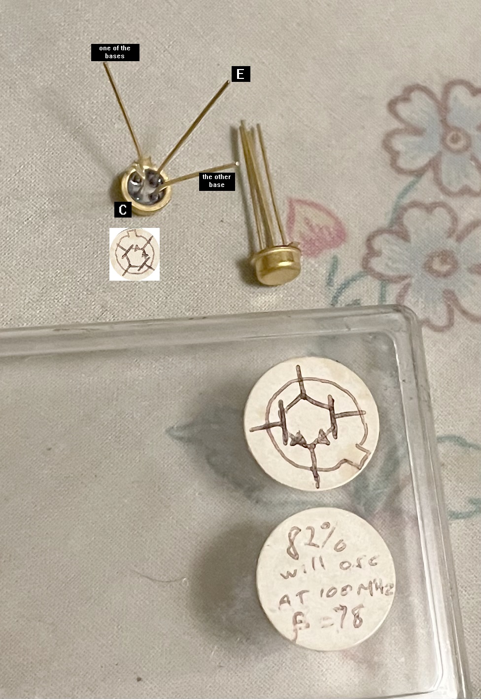
Never have seen a circuit that would use these. Oh, if they had separate collectors
it could be a "differential pair" like you'd find inside an op-amp.